¶ Introduction
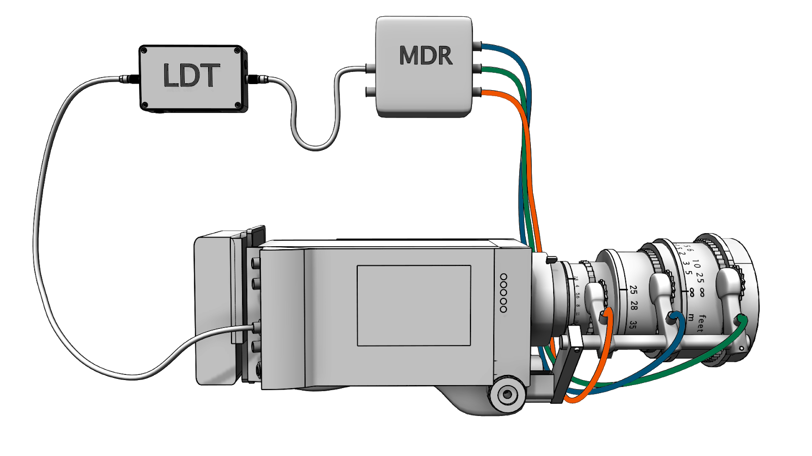
Digital Camera Systems LDT-R2 and LDT-V Series are multi purpose lens encoding systems that can be used for injecting lens data into the RED Family, Panavision DXL, and Sony Venice as well as internal recording for Film cameras and other digital cameras that do not support injection recording. The LDT-V Series can also live stream lens data into virtual production software such as Unreal Engine either wired or wirelessly (LDT-RX1 reciever required for wireless data transmission).
The LDT-R2 and LDT-V Series reads the Focus, Iris and Zoom motor movements from a FIZ motor controller unit and translates this information into human readable encoded data.
This lens metadata can be written directly into the raw camera files in real-time (injection recording) or recorded onto a MicroSD card (Internal SD recording), this can also be streamed live for use in Virtual Production (VP) applications.
This manual is divided into three main sections depending on how the metadata is being recorded. Please go to the appropriate chapters.
Please note, the LDT-V Series has all the functionality of the LDT-R2 but with additional streaming capabilities. In order for the manual to be succinct, the LDT-R2 is referenced when describing functions and features of both models, whereas the LDT-V Series is referenced when it only applies to the LDT-V Series.
¶ LDT-R2/LDT-V Series Compatibility
- Preston MDR-3/MDR-4/MDR-5
- Preston HU3
- Preston HU4
- Arri cforce via LCUBE
- Cmotion cPRO - via LCUBE
- Cmotion Camin One - via LCUBE
- Cmotion DXL2 Module
- Cmotion Camin 3
- Tilta Nucleus-M
- Smart Lenses with a port
- Red Camera Family
- Panavision DXL
- Sony Venice
- All Cameras when internally recording
LDT-V Series Compatibility
- As above
- DCS Unreal Engine Plugin
- Disguise
- Stage Precision
- Aximmetery
Please contact DCS for more information if your device is not listed here.
¶ LDT-R2 Components
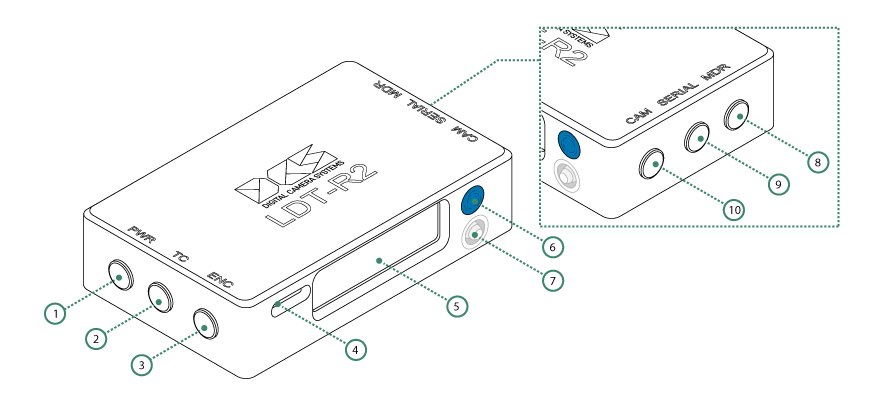
| 1 | Power - 6-pin 0B Lemo | 6 | Back Button |
| 2 | Timecode - 5-pin 0B Lemo | 7 | Joystick |
| 3 | ENC - 6-pin 0B Lemo | 8 | MDR - 4-pin 0B Lemo |
| 4 | Memory slot for MicroSD Card | 9 | Serial - 4-pin 0B Lemo |
| 5 | LCD Screen | 10 | Camera - 4-pin 0B Lemo |
¶ LDT-V Series Components
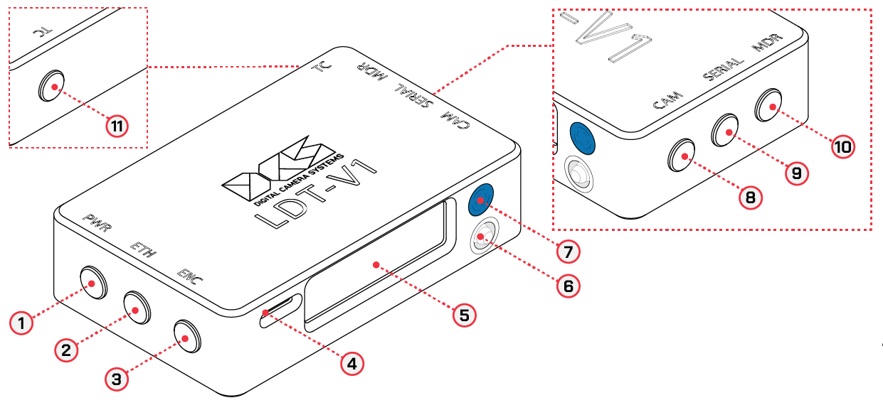
| 1 | Power - 6-pin 0B Lemo | 7 | Back Button |
| 2 | Ethernet - 5-pin 0B Lemo | 8 | Camera - 4-pin 0B Lemo |
| 3 | ENC - 6-pin 0B Lemo | 9 | Serial - 4-pin 0B Lemo |
| 4 | Memory slot for MicroSD Card | 10 | MDR - 4-pin 0B Lemo |
| 5 | LCD Screen | 11 | Timecode - 5-pin 0B Lemo |
| 6 | Joystick | 12 | Antenna (not pictured - LDT-V2 only) |
¶ Physical Connections, Power Voltage and Communication
| Name | Type | Description | Cable Codes | Power Voltage | Communication | Pin Diagram |
|---|---|---|---|---|---|---|
| PWR | 6-pin 0B Lemo / EGG.0B.306 | Power and Shutter Pulse/Rec Tally connector | RUNA, RUNPV, RUNPVY, RUNV, PWRA, PWRC | 6-36V | N/A | 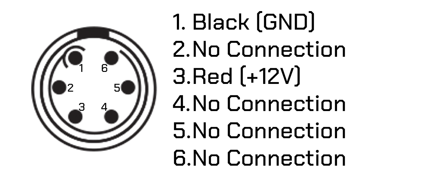 |
| CAM | 4-pin 0B Lemo / EGG.0B.304 | Digital camera connection port | DXL, RED, C/iT, CiPV, SVH | N/A | RS232 |  |
| ENC | 6-pin 0B Lemo / EGG.0B.306 | Lens data encoder connection port for LDT-E Series | ENC | 5V | N/A | 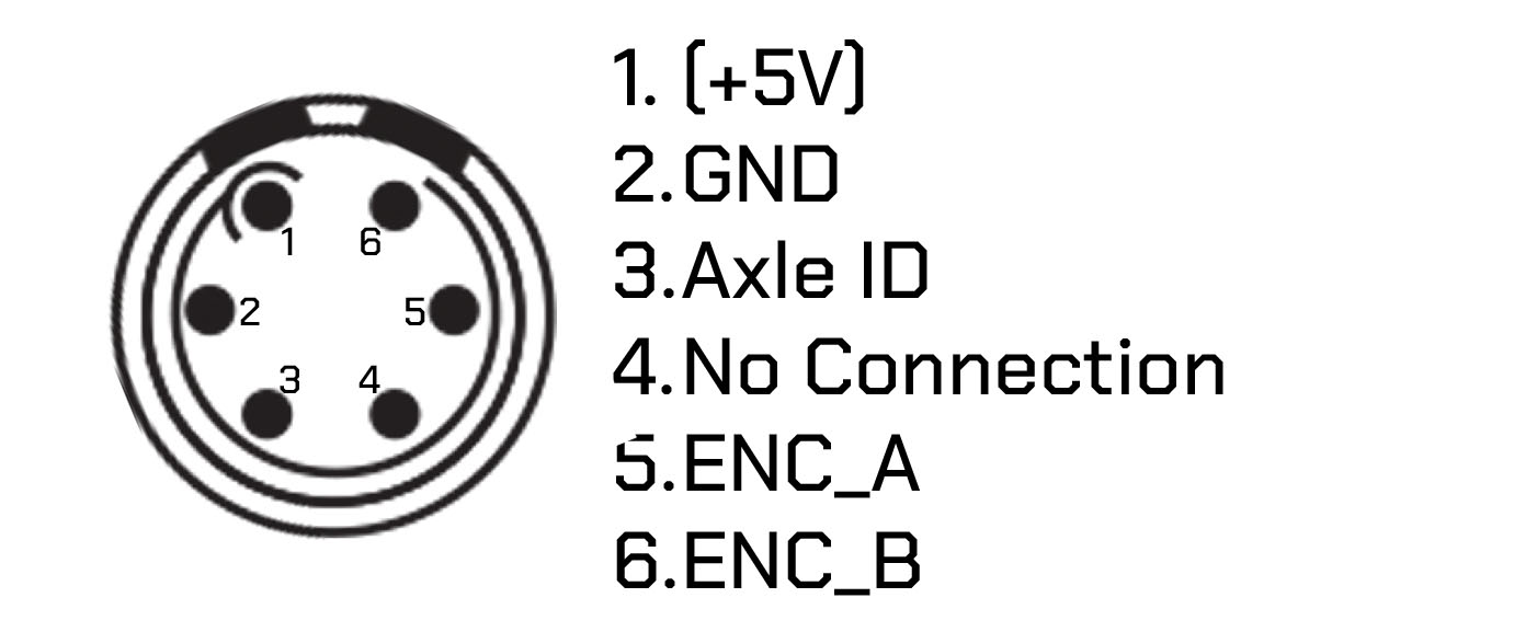 |
| TC | 5-pin 0B Lemo / EGG.0B.305 | Timecode input port | TCD, TCDYA, TCDYB, TCDYC | 0.52-2.12V | N/A | 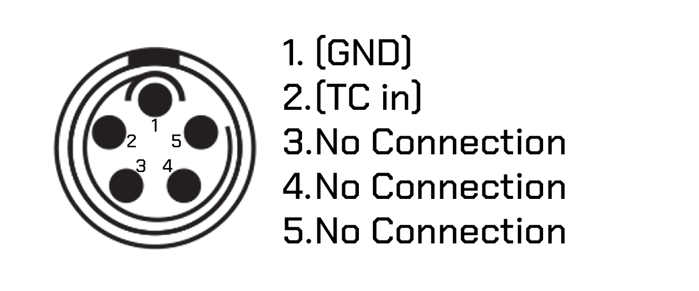 |
| MDR | 4-pin 0B Lemo / EGG.0B.304 | Preston MDR Serial connection port | MDRP | 12V | RS232 |  |
| SERIAL | 4-pin 0B Lemo / EGG.0B.304 | Serial passthrough connection port | CT | 12V | RS232 |  |
| ETH (LDT-V Series Only) | 5-pin 0B Lemo / EGG.0B.305 | Ethernet connection port | EVP | (+/-6V) | 10/100 |  |
¶ Cable Types and Codes
All DCS cables are categorized using a code and a bend relief color for each of the cable types. Cables have two default lengths, 12 or 18 inches and the connector type can be straight (S), right angle (R), or anglissimo (O). Custom cables can be made upon request.
| Code | Bend Relief Color | Type Port Name |
LDT-R2 Rec Mode | Description |
|---|---|---|---|---|
| RUNA | Grey | 6-pin 0B Lemo to 3-pin S102 Fischer PWR |
Film, SD card | RUNA connects the LDT-R2 PWR port to a 3-pin RS socket that provides shutter pulse and power for the unit. If LDT-R2 Rec Mode is set to Injection Recording, RUNA can be used as a power cable. If using the Panavision DXL please use the PWRB cable. |
| RUNPV | Grey | 6-pin 0B Lemo to 10-pin 2S Lemo PWR |
Film, SD card | RUNPV connects the LDT-R2 PWR port to a Panavision Millennium XL2 or other Panavision film cameras. The 10-pin socket on the camera provides shutter pulse and power for the LDT-R2. If the shutter pulse is sent to the camera from a Preston MDR, a Panavison 10-pin splitter box must be used on the camera end. |
| RUNPVY | Grey | 6-pin 0B Lemo to 10-pin S2 Lemo and 10-pin 1B Lemo PWR |
Film, SD card | RUNPVY is a Y cable. It is the same as the RUNPV, but it also connects the 10-pin socket on the camera to a Preston MDR-3 and MDR-4. This lets the shutter pulse travel from the MDR-3 to the camera and LDT-R2 without using a Panavison 10-pin splitter box. |
| RUNV | Grey | 6-pin 0B Lemo to 4-pin Hirose PWR |
Venice, SD card | RUNV connects the LDT-R2 PWR port to the 4-pin Hirose socket of the Sony Venice that provides record tally and power for the unit. |
| PWRA | Black | 6-pin 0B Lemo to 2-pin 0B Lemo PWR |
RED ET, DXL ET, Any Cam Cooke /i | PWRA provides power to the LDT-R2 from a 2-pin 0B Lemo 12v power source. |
| PWRB | Black | 6-pin 0B Lemo to 3-pin S102 Fischer PWR |
DXL ET, Film, SD | PWRB connects the LDT-R2 PWR port to a 3-pin RS socket on a Panavision DXL and provides shutter pulse and power for the unit |
| PWRC | Black | 6-pin 0B Lemo to 3-pin S102 Fischer PWR |
RED ET, DXL ET, Any Cam Cooke /i | PWRC provides power to the LDT-R2 from a 3-pin S102 Fischer 24v power source. |
| DXL | Grey | 4-pin 0B Lemo to 7-pin 1B Lemo CAM |
DXL, Element Technica | DXL cable connects the LDT-R2 to a Panavision DXL. It injects the encoded data into the RAW file. |
| RED | Grey | 4-pin 0B Lemo to 4-pin 00 Lemo CAM |
RED, Element Technica | RED cable connects the LDT-R2 to a RED camera. It injects the encoded data into the RAW file. |
| ENC | Green | 6-pin 0B Lemo to 6-pin 0B Lemo ENC |
Any mode | ENC cable connects the LDT-E Series to the LDT-R2. For more information read: Using a Lens Data Encoder |
| TCD | Brown | 5-pin 0B Lemo to 5-pin 0B Lemo TC |
Film, SD card | TCD sends the timecode signal from a timecode generator to the LDT-R2. |
| TCDYA | Brown | 5-pin 0B Lemo to 5-pin 0B Lemo & 5-pin 0B Lemo TC |
Film, SD card, RED, SD card | TCDYA sends the timecode signal from a timecode generator to the LDT-R2 and another device, for example, the Panavision DXL. |
| TCDYB | Brown | 5-pin 0B Lemo to 5-pin 0B Lemo & BNC TC |
RED, SD card | TCDYB sends the timecode signal from a timecode generator to the LDT-R2 and a RED camera with a BNC timecode input connector. |
| TCDYC | Brown | 5-pin 0B Lemo to 5-pin 0B Lemo & RED Sync TC |
RED, SD card | TCDYC sends a timecode signal from a timecode generator to the LDT-R2 and a RED camera with a Sync timecode input connector. |
| MDRP | Blue | 4-pin 0B Lemo to 4-pin 0B Lemo MDR |
Any mode | MDRP cable connects the LDT-R2 to a Preston MDR3/MDR4 serial port. Also provides power. |
| EVP | Yellow | 5-pin 0B Lemo to RJ45 ETH |
Virtual Production | EVP connects the ETH port of the LDT-V Series the RJ45 connector of a computer. |
| SML | Yello | 4-pin 0B Lemo to 4-pin 0B Lemo MDR |
Any mode | SML connects the MDR port of the LDT-V Series to the port of a smart lens. |
| CT | Orange | 4-pin 0B Lemo to 6-pin 1B Lemo SERIAL |
Any mode | CT cable connects the Preston MDR3/MDR4 serial port with a CineTape. This cable connects to the LDT-R2 Serial connector if the Preston MDR serial ports are in use. |
¶ Navigating Menus
The LDT-R2 is equipped with one button and a joystick.
| The blue button is the back button | 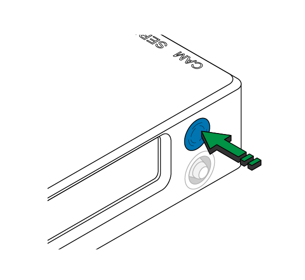 |
| The joystick is used to navigate the menus (up, down, left and right) | 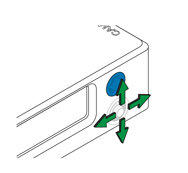 |
| Press the joystick in to access the Menu or select an option | 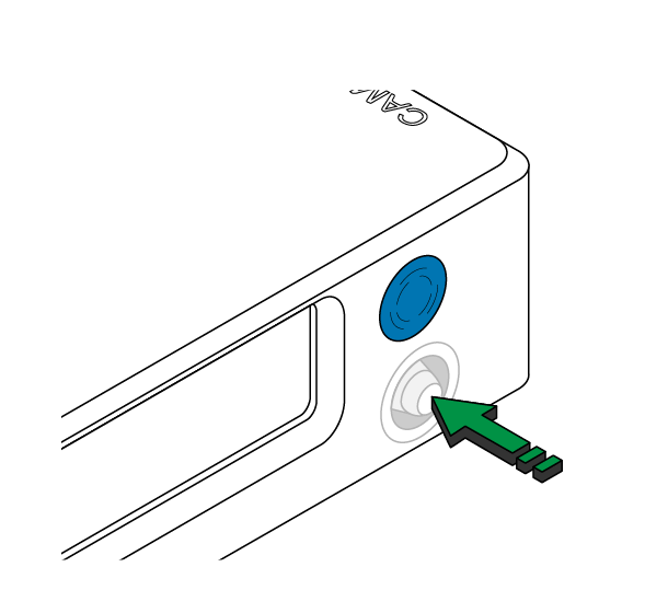 |
Full menu structure can be found in Appendix 1: Menu Structure
¶ Flipping GUI
The GUI of the LDT-R2 will automatically flip when the unit is physically turned over. However, if for rigging purposes the orientation of the screen needs to be fixed then auto-flip can be turned off and an orientation can be selected manually:
Choose: Menu > Settings > Advanced > Flip GUI > Auto / No / Yes
¶ Homepage functions
The homepage comes up when the LDT-R2 powers up. There are four pages.
Depending on the REC Mode selected, the homepage layout differs.
| System Status This page is to check the status of the SD Card and the Preston Connections |
 |
| Selected lens Once a lens is loaded, it will be possible to check the lens details here |
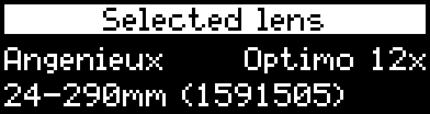 |
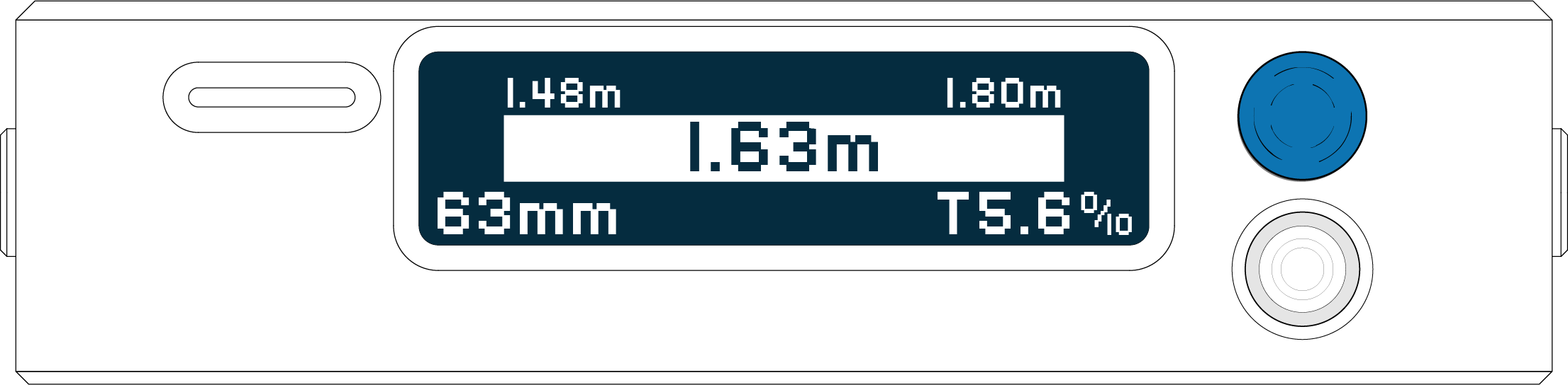
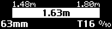
| Lens details Once a lens is encoded the screen will display a real time readout of the three axis’. Push the back button to switch between units measured (feet/metres) |
 |
| Motor Status From this page the motor connection can be checked: - None: No motor detected - Caling: Motor is calibrating - OK: Motor is ready |
 |
On the homepage: joystick Up/Down controls the brightness of the LDT-R2 screen.
¶ Firmware update
DCS ships all units with the latest firmware, but we are constantly working on new features and fixes, so it is highly recommended that you check the firmware is up to date before starting.
¶ Checking the current firmware on the LDT-R2
- Select
Menu > Info, - Firmware will be displayed here.
¶ To update the LDT-R2 firmware
On a computer:
- Download the latest firmware from here,
- Remove the MicroSD Card from the LDT-R2 and insert it into the computer,
- If you are using a brand new MicroSD card format it FAT32,
- Create a folder called ‘FIRMWARE’ on the MicroSD card,
- Copy the firmware into the ‘FIRMWARE’ folder,
- Eject the MicroSD card.
On the LDT-R2:
- Switch off the unit by removing the power cable from the PWR port,
- Insert the MicroSD card back into the LDT-R2,
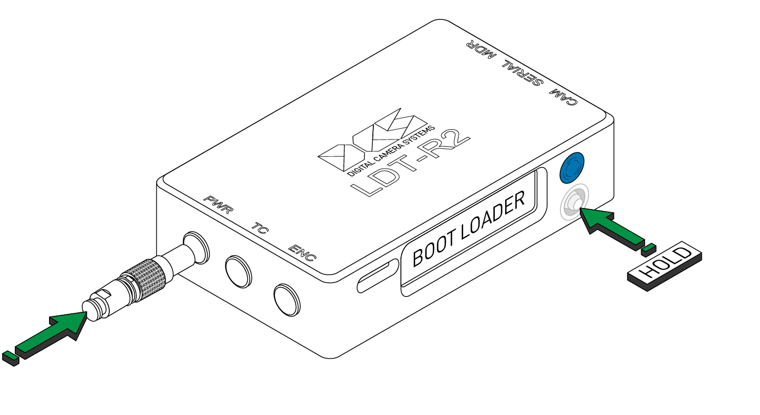
- Push and hold the joystick when powering up the LDT-R2,
- This will take you into the firmware update mode,
- Select the firmware file from the list,
- Press the joystick in to run the update,
- When firmware is updated, reboot the unit by unplugging and replugging the power cable.
¶ Firmware Update Steps
When updating the firmware, it is important that the following steps are followed.
- Update the LDT to the latest firmware,
- Format the SD card on the LDT: (Settings > Advanced > Format SD Card),
- Restore factory defaults (Settings > Advanced > Factory Defaults).
¶ Restoring Factory Defaults
To restore the factory default settings:
- Choose:
Menu > Advanced > Factory Defaults
The required settings will need to be selected on the LDT after this.
¶ The MicroSD Card
¶ Recommended MicroSD Card
DCS recommends any Class 10 MicroSD card. 16gb will be enough capacity for a day’s worth of recording.
The MicroSD Card used should not exceed 32gb.
The system uses FAT32, so larger sizes can cause issues.
¶ Formatting the MicroSD Card
When using Internal Sidecar Recording, the SD Card MUST be formatted each day after the data has been backed up.
This can either be done on the LDT-R2 itself or on a computer.
On the LDT-R2:
- Insert the SD Card;
- Power the LDT-R2;
- Choose:
Menu > Advanced > Format SD Card - Follow the onscreen prompts.
On a computer:
- Insert the SD Card;
- Format the card to FAT16 or FAT32;
- Create 2 folders called:
CLIPSandFIRMWARE
¶ Setting up the Preston MDR and Hand Unit
It is essential that all Preston MDR and HU firmware is updated prior to building any lens tables or F-Maps. There is a known issue where auto lens select will not work when the Preston units are not updated.
All F-maps must be made on one hand unit and shared to the other units.
Save all F-Maps to the "Other > User" folder to ensure auto lens select feature works.
The Preston HU4 cannot input '.5' half lengths. This means that Auto Lens Select should not be used with these F-maps as they would be inaccurate.
- Setup the Focus / Iris / Zoom direction for normal use on the Preston.
- For lens encoding connect the iris and zoom handsets (not required for normal operation).
- Ensure the motor directions are correct on all handsets.
¶ Serial Loop Through for 3rd Party Devices
If no serial port is available on the MDR, the LDT-R2 has a serial loop through port to connect 3rd party devices. Connect the 3rd party device to the serial port of the LDT-R2 and ensure loop through is enabled:
- Choose:
Menu > Settings > SERIAL port > MDR LOOP
¶ CineRT
There is a known issue between the CineRT and LDT-R2 where data will not show up when connected. If this happens, check the CineRT is set to
Serial Out > MDR. If this does not resolve the issue, connect everything up as normal then power cycle the LDT-R2.
-
If used with a Preston lens control workflow, the LDT can power the CineRT through it's serial pass-through via an MDRP cable.
-
If using an a lens control workflow that requires an LCUBE, the CineRT can be powered either by connecting it to a RIA-1 or connecting it to a second LCUBE.
The LCUBE which is connected to the LDT unit MUST be at the end of the chain.
¶ Using a Light Ranger with the LDT-R2
It is recommended that the Light Ranger is used through the serial port of the Preston MDR-3 or MDR-5.
If the LDT's serial pass-through is required, then please get in touch with DCS.
- Email: info@dcs.film
- Phone: +44 (0) 20 8895 6592
DCS would encourage that this setup is fully tested before production begins, to detect any compatibility issues with the user’s setup.
¶ Smart Lens Data Recording/Streaming
The LDT-R2 can record and the LDT-V Series can record and stream data from smart lenses with an external port. Lens tables are not required when using these lenses as all data is passed from the lens to the LDT.
A smart lens must be powered from the camera in order to send data to the LDT.
¶ Connecting a smart lens to the LDT-R2
- Connect the smart lens to the LDT-R2 MDR port with the SML (yellow) cable
¶ Setting up the LDT-R2
Push the joystick in to enter the menu, use the back button to go back.
- Choose:
Menu > Settings > Advanced > Data source > Pull from lens
¶ Using Cmotion Camin with CLM Motors (non-LBUS)
Please note that lens tables do not need to be built on the LDT-R2 in this configuration as lens data is pulled from the Cmotion or WCU4 handset.
Do not connect an LDT-E Series to the LDT-R2 in this configuration as it will clear incoming lens data.
¶ Camin3
¶ Connecting Camin3 to the LDT-R2
- Connect the EXT port on the Camin3 to the LDT-R2 MDR port with the CM (orange) cable.
¶ Setting up the LDT-R2
Push the joystick in to enter the menu, use the back button to go back.
- Choose:
Menu > Settings > Advanced > Data source > Pull from Camin
¶ DXL2 Module
¶ Connecting DXL2 Module to the LDT-R2
- Connect the CBUS port on the DXL camera to the LDT-R2 MDR port with the CM (orange) cable.
¶ Setting up the LDT-R2
Push the joystick in to enter the menu, use the back button to go back.
- Choose:
Menu > Settings > Advanced > Data source > Pull from DXL cmotion
¶ Connecting Camin3 to the LDT-R2
- Connect the Serial port on the Camin One or cPRO to the LDT-R2 MDR port with the CML (blue) cable.
¶ Using Arri Lens Control, Cmotion Camin One or cPRO Camin (LBUS)
Lens tables must to be built on the LDT-R2 for this configuration.
¶ For LCUBE
- Connect the Arri motors together via LBUS cables,
- Connect an LCUBE at the end of the motor chain,
- Connect the Serial port of the LCUBE to the LDT-R2 MDR port with the CML (blue) cable.
The LCUBE should be connected at the end of the motor chain.
Ensure the LDT is connected to the LCUBE's serial port before powering it on. This will ensure that the LCUBE sends the relevant data.
¶ Connecting Camin One or cPRO Camin to the LDT-R2
- Connect the Camin One or cPRO Camin to the motors,
- Connect the motors to the LCUBE LBUS port,
- Connect the Serial port on the LCUBE to the LDT-R2 MDR port with the CML (blue) cable.
The LCUBE should be connected at the end of the motor chain.
¶ Setting up the LDT-R2
Push the joystick in to enter the menu, use the back button to go back.
- Choose:
Menu > Settings > Advanced > Data source > Pull from LCUBE
¶ Using a Tilta Nucleus-M
¶ Connecting Tilta Nucleus-M to the LDT-R2
Please ensure the handset it running the latest available firmware
- Connect the Nucleus-M to the LDT-R2 MDR port with the TNM (Blue) cable
¶ Setting up the LDT-R2
Push the joystick in to enter the menu, use the back button to go back.
- Choose:
Menu > Settings > Advanced > Data source > Pull from Nucleus-M
The motors must then be linked to the correct FIZ axis.
- Choose:
Menu > Motor/LDE setup > Focus - Choose:
Menu > Motor/LDE setup > Iris - Choose:
Menu > Motor/LDE setup > Zoom
From here MOT 1 - MOT 4 can be selected in accordance with the motor mapping that is set on the Nucleus-M controller.
The motor direction can be set to normal or reverse if required.
¶ Lens Link Support
This setup requires the LDT-V2 instead of the LDT R2.
The LDT-V2 is directly compatible with the Lens Link workflow to enable motor control at a greater range.
If using the LDT-R2, please exchange this for an LDT-V2 unit instead. The cables and camera connection workflow is the same between units.
For further guidance on this workflow, please refer to the Lens Link Manual.
¶ Injection Recording
Refer to this section if you are recording data externally from the LDT-R2. This mode is only available for digital cameras.
In this chapter you can find details on how to set up a camera in order to record metadata into the raw file headers, depending on the system you are running.
¶ RED Camera Family
For the RED V-RAPTOR please follow the instructions here.
¶ Setting up the Camera
There is known issue with the RED Camera that stops lens data being displayed. Please ensure that the camera is running firmware 7.02 or later.
- Connect the RED Touch to access all of the camera settings.
¶ Enabling ET Protocol
In order to enable the LDT-R2 to talk to the camera and to write and display lens metadata, the ET Protocol must be selected:
- From the LCD choose:
Menu > Settings > Setup > Communication > Serial - From the
Ctrl Protocolselect:Element Technica
¶ Disabling the Lens Mount
To avoid lenses interfering with the LDT, the smart lens mount needs to be disabled:
- From the LCD choose:
Menu > Settings > Setup > Lens - Untick
Enable Power to LensandAuto-Detect PL Lenses
Don’t worry if the menu is grayed out. This means a smart lens mount is not fitted to the camera.
¶ Overlay Lens Data on a Monitor
In order to display lens data as an overlay on an SDI monitor, do the following:
- Download the overlay here;
- Copy the ‘overlay’ folder into a fresh
REDMAG - Load the camera mag into the camera;
- Choose
Menu > Settings > Display > Monitor Control > Overlays - Move the
On Mediaoverlay toIn Camera - Choose
Menu > Settings > Display > Monitor Control > Monitor Setup - Select HD-SDI from the top left dropdown menu,
- On Overlay choose DCS.
¶ Rigging the LDT-R2
- Connect the camera CTRL/CNTL port to the LDT-R2 CAM port with the RED (gray) cable;
- Power the LDT-R2 with the PWRA or PWRC cable to a 2-pin or Dtap power source.
Please note that if you require a longer RED cable, the maximum working length is 6ft.
¶ For Preston
- Connect the MDR to the LDT-R2 MDR port with the MDRP (blue) cable.
¶ For LCUBE
- Connect the LCUBE Serial port to the LDT-R2 MDR port with the CML (blue) cable.
The LCUBE should be connected at the end of the motor chain.
¶ For Camin One or cPRO Camin
- Connect the Camin One or cPRO Camin to the motors,
- Connect the motors to the LBUS port of the LCUBE,
- Connect the LCUBE Serial port of the the LDT-R2 MDR port with the CML (blue) cable.
The LCUBE should be connected at the end of the motor chain.
¶ For Camin3
- Connect the EXT port of the Camin3 to the LDT-R2 MDR port with the CM (orange) cable.
Please note that lens tables do not need to be built on the LDT-R2 in this configuration as lens data is pulled from the Cmotion or WCU4 handset.
Do not connect an LDT-E Series to the LDT-R2 in this configuration as it will clear incoming lens data.
¶ Setting up the LDT-R2
Push the joystick in to enter the menu, use the back button to go back.
- Choose:
Menu > Settings > MODE > RED, Element Tech
¶ For Preston
- Choose:
Menu > Settings > Advanced > Data source > Local Table
¶ For LCUBE
- Choose:
Menu > Settings > Advanced > Data source > Pull from LCUBE
¶ For Camin3
- Choose:
Menu > Settings > Advanced > Data source > Pull from Camin
¶ Rigging and Settings for a Smart Lens
Follow the instructions above omitting the Preston MDR rigging and Data Source setting. Use the rigging and settings found here to complete set-up.
¶ RED V-RAPTOR and KOMODO
Please note as the LDT-R2 needs a CTRL port to inject data. If port is not available then A RED Expander Blade (or similar product) is required.
RED V-Raptor running 1.3.1(beta) onwards supports injection recording.
RED Komodo running 1.7.5 onwards supports injection recording.
¶ Setting up the Camera
No settings are required to enable lens data injection - plug the LDT-R2 to the camera following the set-up instructions below.
¶ Overlay Lens Data on a Monitor
To enable lens data as an overlay please apply the following communication settings:
-
MENU > Communication > Connections > Serial > Protocol > Network (PPP) -
MENU > Communication > Connections > Serial > Baud rate = 115200 -
MENU > Communication > Connections > Serial > IP Address = 169.254.1.1
Camera must be power cycled to see the affect of the changes.
Then apply the following settings:
V-RAPTOR
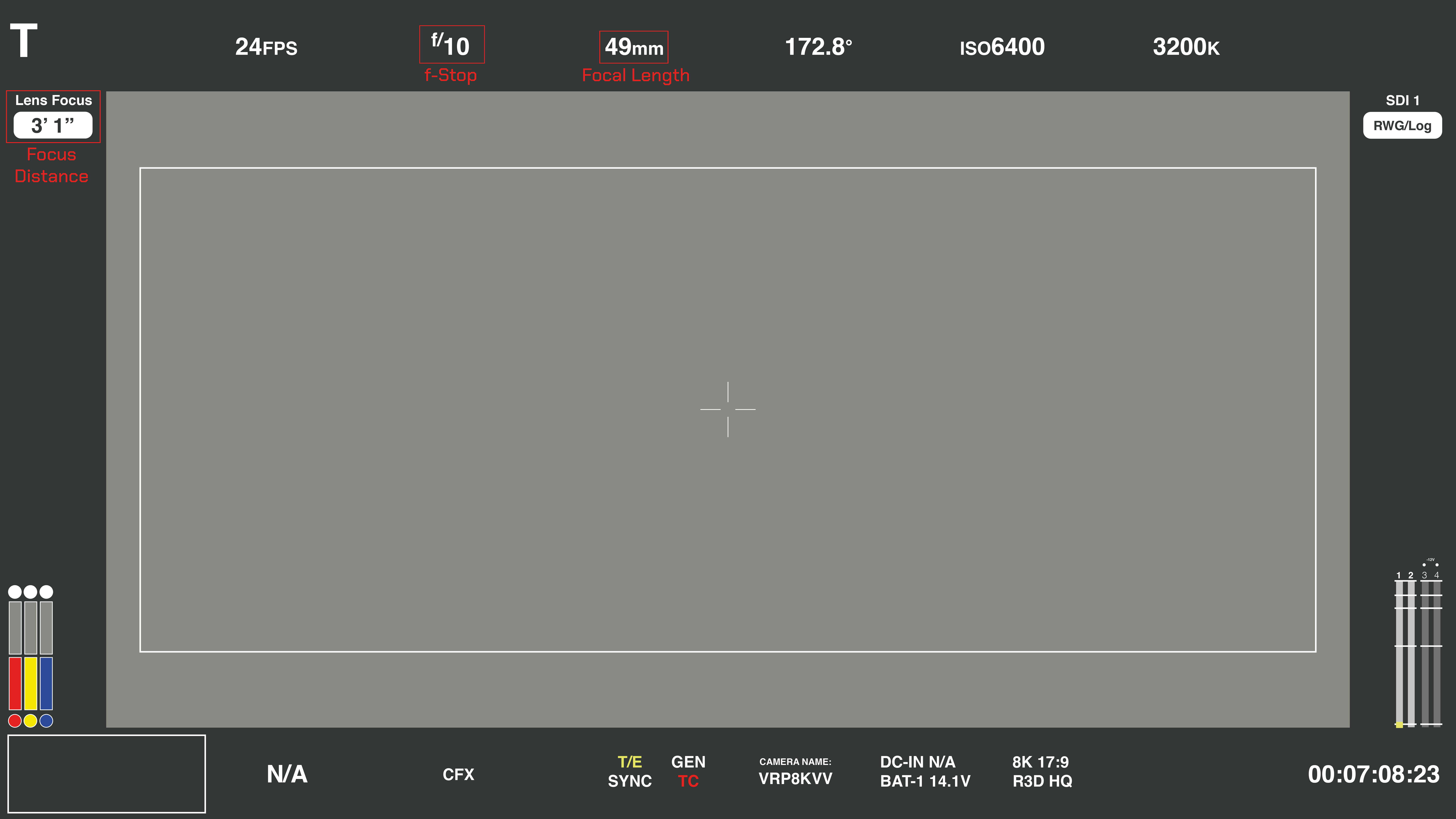
In order to display lens data as an overlay on an SDI monitor, do the following in the V-Raptor menu:
- Choose:
Monitoring > SDI 1/2 > Overlay> Toggle to Green (enabled) - Choose:
Monitoring > SDI 1/2 > Overlay Mode > Technical
¶ Overlay Guide - V-Raptor
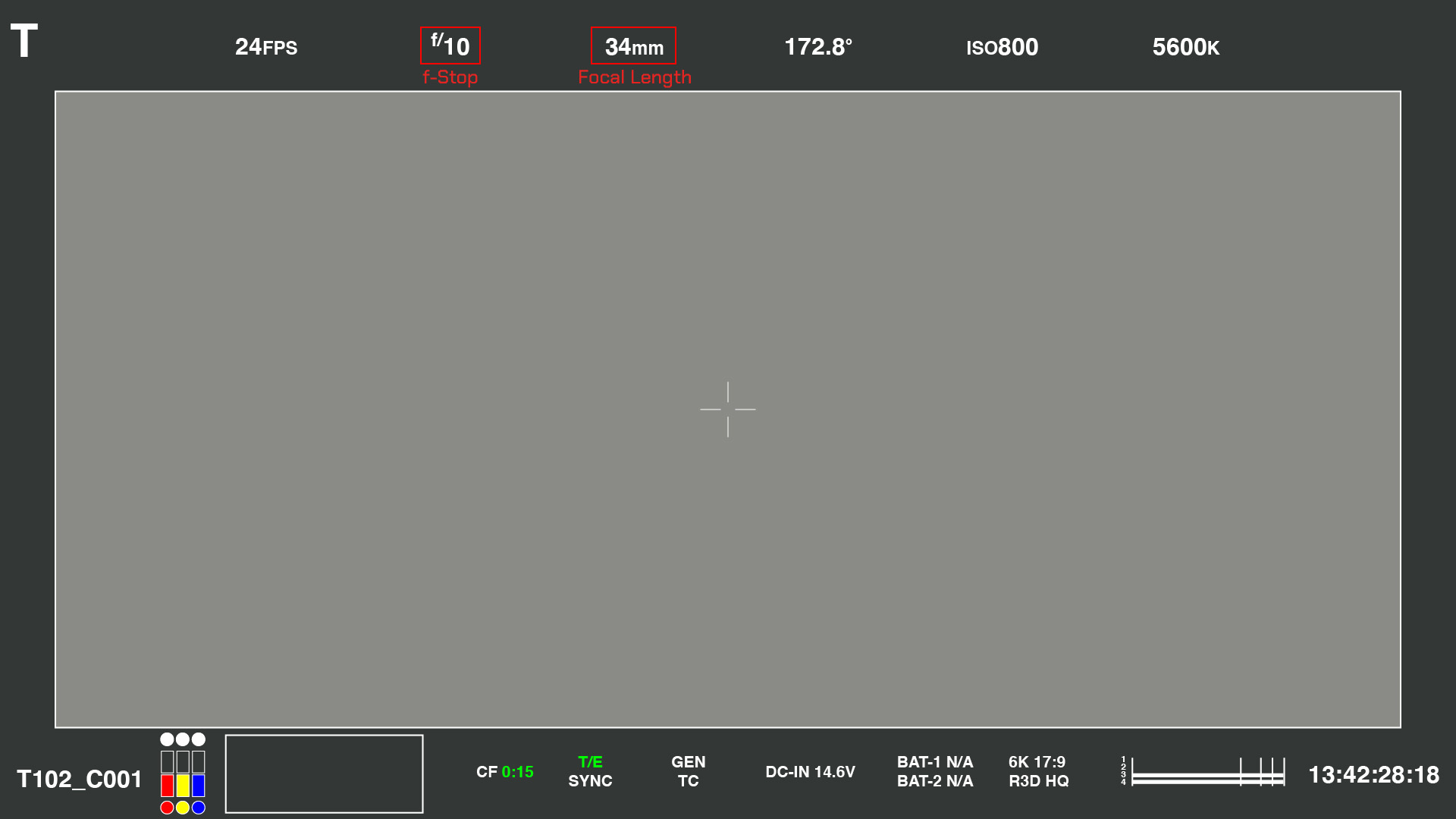
¶ Overlay Guide - Komodo
¶ Rigging the LDT-R2
- Connect the camera CTRL/CNTL port to the LDT-R2 CAM port with the RED (gray) cable;
- Power the LDT-R2 with the PWRA or PWRC cable to a 2-pin or Dtap power source.
Please note that if you require a longer RED cable, the maximum working length is 6ft.
¶ For Preston
- Connect the MDR to the LDT-R2 MDR port with the MDRP (blue) cable.
¶ For LCUBE
- Connect the LCUBE Serial port to the LDT-R2 MDR port with the CML (blue) cable.
The LCUBE should be connected at the end of the motor chain.
¶ For Camin One or cPRO Camin
- Connect the Camin One or cPRO Camin to the motors,
- Connect the motors to the LBUS port of the LCUBE,
- Connect the LCUBE Serial port of the the LDT-R2 MDR port with the CML (blue) cable.
The LCUBE should be connected at the end of the motor chain.
¶ For Camin3
- Connect the EXT port of the Camin3 to the LDT-R2 MDR port with the CM (orange) cable.
Please note that lens tables do not need to be built on the LDT-R2 in this configuration as lens data is pulled from the Cmotion or WCU4 handset.
Do not connect an LDT-E Series to the LDT-R2 in this configuration as it will clear incoming lens data.
¶ Setting up the LDT-R2
Push the joystick in to enter the menu, use the back button to go back.
- Choose:
Menu > Settings> MODE > RED, RCP2
¶ For Preston
- Choose:
Menu > Settings > Advanced > Data source > Local Table
¶ For LCUBE
- Choose:
Menu > Settings > Advanced > Data source > Pull from LCUBE
¶ For Camin3
- Choose:
Menu > Settings > Advanced > Data source > Pull from Camin
¶ Rigging and Settings for a Smart Lens
Follow the instructions for Preston above omitting the Preston MDR rigging and Data Source setting. Use the rigging and settings found here to complete set-up.
¶ Panavision DXL
¶ Setting up the Camera
There is known issue with the Panavision DXL that stops lens data being displayed. Please ensure that the camera is running firmware 1.01.1 or 1.0.2.3.
¶ Enabling ET Protocol
In order to enable the LDT-R2 to talk to the camera and to write and display lens metadata, the ET Protocol must be selected:
- From the side panel choose:
Menu > Network > Serial - From
Ctrl ProtocolselectElement Technica.
¶ Disabling the Lens Mount
To avoid lenses interfering with the LDT, the lens mount needs to be disabled:
- From the LCD choose:
Menu > Setting > Setup > Lens - Choose:
Disable lens mount
Don’t worry if the menu is grayed out. It means a smart lens mount is not fitted to the camera.
¶ Overlay Lens Data on a Monitor
In order to display lens data as an overlay on an SDI monitor, do the following:
- Download the overlay here;
- Copy the ‘overlay’ folder into a fresh
REDMAG - Load the camera mag into the camera;
- Choose
Menu > Settings > Display > Monitor Control > Overlays - Move the
On Mediaoverlay toIn Camera - Choose
Menu > Settings > Display > Monitor Control > Monitor Setup - Select HD-SDI from the top left dropdown menu,
- On Overlay choose DCS.
¶ Rigging the Camera to the LDT-R2
- Connect the camera AUX port to the LDT-R2 CAM port with the DXL (gray) cable;
- Power the LDT-R2 with the PWRA or PWRC cable to a 2-pin or Dtap power source.
¶ For Preston
- Connect the MDR to the LDT-R2 MDR port with the MDRP (blue) cable.
¶ For LCUBE
- Connect the LCUBE Serial port to the LDT-R2 MDR port with the CML (blue) cable.
The LCUBE should be connected at the end of the motor chain.
¶ For Camin One or cPRO Camin
- Connect the Camin One or cPRO Camin to the motors,
- Connect the motors to the LBUS port of the LCUBE,
- Connect the LCUBE Serial port of the the LDT-R2 MDR port with the CML (blue) cable.
The LCUBE should be connected at the end of the motor chain.
¶ For Camin3
- Connect the EXT port of the Camin3 to the LDT-R2 MDR port with the CM (orange) cable.
Please note that lens tables do not need to be built on the LDT-R2 in this configuration as lens data is pulled from the Cmotion or WCU4 handset.
Do not connect an LDT-E Series to the LDT-R2 in this configuration as it will clear incoming lens data.
¶ For DXL Cmotion Camin Module
- Connect the CBUS port on the DLX camera to the LDT-R2 MDR port with the CM (orange) cable.
Please note that lens tables do not need to be built on the LDT-R2 in this configuration as lens data is pulled from the Cmotion or WCU4 handset.
Do not connect an LDT-E Series to the LDT-R2 in this configuration as it will clear incoming lens data.
¶ Setting up the LDT-R2
Push the joystick in to enter the menu, use the back button to go back.
- Choose:
Menu > Settings> MODE > DXL, Element Tech
¶ For Preston
- Choose:
Menu > Settings > Advanced > Data source > Local Table
¶ For LCUBE
- Choose:
Menu > Settings > Advanced > Data source > Pull from LCUBE
¶ For Camin3
- Choose:
Menu > Settings > Advanced > Data source > Pull from Camin
¶ For DXL Cmotion Module
- Choose:
Menu > Settings > Data source > Pull from DXL cmotion
¶ Rigging and Settings for a Smart Lens
Follow the instructions for Preston above omitting the Preston MDR rigging and Data Source setting. Use the rigging and settings found here to complete set-up.
¶ Sony Venice/Venice 2/Burano - Lens Mount Injection
In order to inject data into the body of the camera a specialist lens mount is required. Please discuss with the rental house your options or contact DCS directly.
Supported Lens Mounts for this workflow include Panavison 4-pin and 9-pin mounts as well as Wooden Camera's 4-pin mount.
¶ Setting up the Lens Mount
Depending on the lens mount being used, ensure any physical switch is set to EXT.
¶ Setting up the Camera
Sony Venice does not require any setting up to accept the Cooke /i information coming from the 4-pin or 9-pin LEMO installed on the lens mount.
¶ Overlay Lens Data on a monitor - Venice/Venice 2/Burano
In order to display lens data as overlay on a SDI monitor, do the following:
- Choose:
Menu > Monitoring - Select the desired SDI output;
- Press down the control knob and select
Setup - Navigate to
Lens Statusand checkInfo - Choose the desired unit of measurement, the default is feet.
If there is no lens data on the monitor or camera when a lens table is loaded on the LDT-R2, check the following setting on the Sony Venice body:
Long press
Menu>Technical>Lens Configuration > PL Mt Interface Position > Top.
¶ Overlay Guide - Sony Venice

¶ Rigging the LDT-R2
- Power the LDT-R2 using the PWRA or PWRC cable to a 2-pin or Dtap power source.
¶ Panavision 9-pin Smart Mount
- Use the CiPV (yellow) cable to connect the Sony Venice’s lens mount to the LDT-R2's CAM port;
If using a 4-pin Panavision Smart Mount, contact DCS for specific instructions.
¶ Wooden Camera 4-pin Smart Mount
- Use the SML (yellow) cable to connect the Sony Venice’s lens mount to the LDT-R2's CAM port;
¶ For Preston
- Connect the MDR to the LDT-R2 MDR port with the MDRP (blue) cable.
¶ For LCUBE
- Connect the LCUBE Serial port to the LDT-R2 MDR port with the CML (blue) cable.
The LCUBE should be connected at the end of the motor chain.
¶ For Camin One or cPRO Camin
- Connect the Camin One or cPRO Camin to the motors,
- Connect the motors to the LBUS port of the LCUBE,
- Connect the LCUBE Serial port of the the LDT-R2 MDR port with the CML (blue) cable.
The LCUBE should be connected at the end of the motor chain.
¶ For Camin3
- Connect the EXT port of the Camin3 to the LDT-R2 MDR port with the CM (orange) cable.
Please note that lens tables do not need to be built on the LDT-R2 in this configuration as lens data is pulled from the Cmotion or WCU4 handset.
Do not connect an LDT-E Series to the LDT-R2 in this configuration as it will clear incoming lens data.
If using the 9-pin Sony Venice smart mount, there is a dip switch on the side which can select "LENS" and "EXT". It is recommended this be set to "LENS" under normal operation. In this setting, data from a smart lens will overide the LDT data from the port. To deactivate the smart lens pins select "EXT".
¶ Setting up the LDT-R2
Push the joystick in to enter the menu, use the back button to go back.
- Choose:
Menu > Settings> MODE > Cooke /i
¶ For Preston
- Choose:
Menu > Settings > Advanced > Data source > Local Table
¶ For LCUBE
- Choose:
Menu > Settings > Advanced > Data source > Pull from LCUBE
¶ For Camin3
- Choose:
Menu > Settings > Advanced > Data source > Pull from Camin
¶ Rigging and Settings for a Smart Lens
Follow the instructions above omitting the Preston MDR rigging and Data Source setting. Use the rigging and settings found here to complete set-up.
¶ Sony Venice/Venice 2 - Venice Body Injection
Due to limitations with this method, iris values are transmitted as F-stops rather than T-stops, serial data cannot be injected, and the lens name will display as 'DCS'. For applications requiring accurate lens naming and T-stop data, the Lens Mount injection method is recommended.
All cables MUST be connected before the camera turns on.
If any cables are unplugged, or the LDT is rebooted while the camera is on, the camera MUST be power cycled.
The LDT MUST be powered directly from the battery/power plate and NOT from the camera.
¶ Setting up the Camera
The required setting can be accessed by holding the Menu button for 2 seconds.
Menu > Technical > Lens Configuration > Lens 12pin > ON
¶ Overlay Lens Data on a monitor
In order to display lens data as overlay on a SDI monitor, do the following:
- Choose:
Menu > Monitoring - Select the desired SDI output;
- Press down the control knob and select
Setup - Navigate to
Lens Statusand checkInfo - Choose the desired unit of measurement, the default is feet.
If there is no lens data on the monitor or camera when a lens table is loaded on the LDT-R2, check the following setting on the Sony Venice body:
Long press
Menu>Technical>Lens Configuration > PL Mt Interface Position > Top.
¶ Overlay Guide - Sony Venice
¶ Rigging the LDT-R2
- Connect the Sony Venice’s 12pin Hirose port to the LDT-R2's CAM port with the SVH cable;
- Power the LDT-R2 via the PWR port, using the PWRA or PWRC cable to a 2-pin or Dtap power source.
¶ For Preston
- Connect the MDR to the LDT-R2 MDR port with the MDRP (blue) cable.
¶ For LCUBE
- Connect the LCUBE Serial port to the LDT-R2 MDR port with the CML (blue) cable.
The LCUBE should be connected at the end of the motor chain.
¶ For Camin One or cPRO Camin
- Connect the Camin One or cPRO Camin to the motors,
- Connect the motors to the LBUS port of the LCUBE,
- Connect the LCUBE Serial port of the the LDT-R2 MDR port with the CML (blue) cable.
The LCUBE should be connected at the end of the motor chain.
¶ For Camin3
- Connect the EXT port of the Camin3 to the LDT-R2 MDR port with the CM (orange) cable.
Please note that lens tables do not need to be built on the LDT-R2 in this configuration as lens data is pulled from the Cmotion or WCU4 handset.
Do not connect an LDT-E Series to the LDT-R2 in this configuration as it will clear incoming lens data.
¶ Setting up the LDT-R2
Push the joystick in to enter the menu, use the back button to go back
- Choose:
Menu > Settings > MODE > Venice 12pin
¶ For Preston
- Choose:
Menu > Settings > Advanced > Data source > Local Table
¶ For LCUBE
- Choose:
Menu > Settings > Advanced > Data source > Pull from LCUBE
¶ For Camin3
- Choose:
Menu > Settings > Advanced > Data source > Pull from Camin
¶ Rigging and Settings for a Smart Lens
Follow the instructions above omitting the Preston MDR rigging and Data Source setting. Use the rigging and settings found here to complete set-up.
¶ Internal Recording
Refer to this section if you are recording data in the LDT-R2. This mode is available for all types of cameras. LDT-R2 requires shutter pulse or record tally from the camera in order to start recording data.
A constant external timecode source must be provided to the LDT-R2 by a timecode generator. The LDT-R2 will not receive timecode directly from a camera. This is by design as timecode is lost when going off speed.
Encoded data is recorded on the MicroSD card.
The SD Card MUST be formatted each day after the data has been backed up.
Please make sure to backup the MicroSD data on a computer after each shooting day in order to avoid data loss.
¶ Recording Format
Frame by frame (FbF) data is recorded onto the MicroSD card’s CLIPS folder, as a CSV file type. Everytime the camera runs, a new CSV file is created.
The CSV file is matched to the timecode. A new line gets created at every timecode interval.
Read ‘Appendix 2: Internal Recording - CSV File Structure’ to learn more about it.
¶ Setting up the LDT-R2
Select the desired projects FPS.
- Choose:
Menu > Settings> Project FPS
Choose between:23.98FPS, 24FPS, 25FPS, 29.97FPS, 30FPS
Project FPS must match Timecode FPS.
If running multiple LDT-R2s at once, setting the corresponding camera index is advised.
- Choose:
Menu > Settings> Camera index > A, B, C, ...
Set the roll number on the LDT to the corresponding roll loaded on the camera. This does not require removing or changing the SD card. To set the roll number:
- Choose:
Menu > Settings> Roll > 001, 002, 003, ...
It is essential to change the roll on the LDT every time the roll is changed on the camera so they match. This information is used to link the data in post production.
¶ Recording and Timecode signal
When Internal Recording is set, the LDT-R2 changes the Lens Details homepage to fit the TC and REC icons.
After connecting the timecode cable from a timecode generator device into the TC port on the LDT-R2, the Lens Details homepage will show a stable TC icon meaning that the LDT-R2 is receiving a good timecode. A flashing TC icon means that the LDT-R2 is receiving timecode but at the wrong FPS, change the LDT-R2 or the timecode generator project FPS to match. No TC icon means that the LDT-R2 is not receiving any timecode, check the cable direction if using a unidirectional timecode cable.
When recording a REC icon will pop-up under the TC icon.
¶ Start/Stop Recording from the Preston HU3
If the LDT-R2 cannot receive a record trigger from the camera, then recording can be controlled from a Preston HU3.
To enable the Preston start/stop functionality, on the LDT-R2:
Menu > Settings > Mode > MDR, SD Card- To start recording from the HU3 press the “Camera” button,
- To stop recording press the “Camera” button.
To verify the LDT-R2 is recording:
- REC will appear on the main screen of the LDT-R2 and,
- The LED above the "Camera" button on the HU3 will light up.
When manually starting and stopping the LDT-R2 it is important to limit the clip lengths to match those being recorded by the camera. Recording all day (for instance) can result in loss of data.
¶ Manual Recording on the LDT-R2
If the LDT-R2 cannot receive a record trigger from the camera or the the Preston HU3, recording can be manually started and stopped from the device itself when in any SD Mode.
- To start recording hold the blue "back" button for 3 seconds,
- To stop recording press the blue "back" button.
To verify the LDT-R2 is recording:
- REC will appear on the main screen of the LDT-R2.
When manually starting and stopping the LDT-R2 it is important to limit the clip lengths to match those being recorded by the camera. Recording all day (for instance) can result in loss of data.
¶ Browse Clips
This funtion is allows the user to check that clips are recording to the SD Card as expected.
- Choose:
Menu > Browse clips
¶ Arri Film cameras
When using Internal Sidecar Recording, the SD Card MUST be formatted each day after the data has been backed up.
It is crucial to display a digislate, or at the very least a timecode, within EVERY take. This ensures there is a reference to link the film with the lens data clip.
¶ Rigging the Camera and LDT-R2
Arri film cameras are equipped with a 3-pin RS power out which provides power and shutter pulse for the LDT-R2.
- Connect the RS port on the camera to the LDT-R2 PWR with the RUNA (grey) cable.
- Connect an external timecode source to the LDT-R2 TC port with a Y-Cable that will also feed the camera.
¶ For Preston
- Connect the MDR to the LDT-R2 MDR port with the MDRP (blue) cable.
¶ For LCUBE
- Connect the LCUBE Serial port to the LDT-R2 MDR port with the CML (blue) cable.
The LCUBE should be connected at the end of the motor chain.
¶ For Camin One or cPRO Camin
- Connect the Camin One or cPRO Camin to the motors,
- Connect the motors to the LBUS port of the LCUBE,
- Connect the LCUBE Serial port of the the LDT-R2 MDR port with the CML (blue) cable.
The LCUBE should be connected at the end of the motor chain.
¶ For Camin3
- Connect the EXT port of the Camin3 to the LDT-R2 MDR port with the CM (orange) cable.
Please note that lens tables do not need to be built on the LDT-R2 in this configuration as lens data is pulled from the Cmotion or WCU4 handset.
Do not connect an LDT-E Series to the LDT-R2 in this configuration as it will clear incoming lens data.
¶ Setting up the LDT-R2
Push the joystick in to enter the menu, use the back button to go back.
- Choose:
Menu > Settings> MODE > Film, SD card
¶ For Preston
- Choose:
Menu > Settings > Advanced > Data source > Local Table
¶ For LCUBE
- Choose:
Menu > Settings > Advanced > Data source > Pull from LCUBE
¶ For Camin3
- Choose:
Menu > Settings > Advanced > Data source > Pull from Camin
¶ Rigging and Settings for a Smart Lens
Follow the instructions above omitting the Preston MDR rigging and Data Source setting. Use the rigging and settings found here to complete set-up.
¶ Panavision Film Camera
When using Internal Sidecar Recording, the SD Card MUST be formatted each day after the data has been backed up.
It is crucial to display a digislate, or at the very least a timecode, within EVERY take. This ensures there is a reference to link the film with the lens data clip.
¶ Rigging the Camera and LDT-R2
Panavision XL2 cameras are equipped with a 10-pin Lemo connector which provides power and shutter pulse for the LDT-R2.
- Use the RUNPVY (gray) cable to connect the 10-Pin Lemo on the camera to the LDT-R2 PWR and to the Preston MDR-3 Camera port. This cable allows the shutter pulse to travel from the MDR-3 to the camera and to the LDT-R2.
- Connect an external timecode source to the LDT-R2 TC port with a Y-Cable that will also feed the camera.
¶ For Preston
- Connect the MDR to the LDT-R2 MDR port with the MDRP (blue) cable.
¶ For LCUBE
- Connect the LCUBE Serial port to the LDT-R2 MDR port with the CML (blue) cable.
The LCUBE should be connected at the end of the motor chain.
¶ For Camin One or cPRO Camin
- Connect the Camin One or cPRO Camin to the motors,
- Connect the motors to the LBUS port of the LCUBE,
- Connect the LCUBE Serial port of the the LDT-R2 MDR port with the CML (blue) cable.
The LCUBE should be connected at the end of the motor chain.
¶ For Camin3
- Connect the EXT port of the Camin3 to the LDT-R2 MDR port with the CM (orange) cable.
Please note that lens tables do not need to be built on the LDT-R2 in this configuration as lens data is pulled from the Cmotion or WCU4 handset.
Do not connect an LDT-E Series to the LDT-R2 in this configuration as it will clear incoming lens data.
Alternatively, Panavision provides a splitter box to duplicate the 10-pin lemo on the camera. If available, use the RUNPV (gray) cable to connect the 10-Pin Lemo on the camera to the LDT-R2 PWR. Plug the MDR 3 as per usual.
¶ Setting up the LDT-R2
Push the joystick in to enter the menu, use the back button to go back.
- Choose:
Menu > Settings > MODE > Film, SD card
¶ For Preston
- Choose:
Menu > Settings > Advanced > Data source > Local Table
¶ For LCUBE
- Choose:
Menu > Settings > Advanced > Data source > Pull from LCUBE
¶ For Camin3
- Choose:
Menu > Settings > Advanced > Data source > Pull from Camin
¶ Rigging and Settings for a Smart Lens
Follow the instructions above omitting the Preston MDR rigging and Data Source setting. Use the rigging and settings found here to complete set-up.
¶ RED Family
DCS always advise to use injection recording on RED cameras. However, if the production requires frame by frame data to be recorded internally on the SD card of the LDT-R2 follow the procedure below.
When using Internal Sidecar Recording, the SD Card MUST be formatted each day after the data has been backed up.
¶ Setting up the Camera
RED cameras can send out Rec Tally from the CTRL port. In order to allow the LDT-R2 to receive a recording signal from the camera and to write metadata, the RED Command Protocol (RCP) must be enabled.
- Connect the RED Touch to access all of the camera settings;
- From the LCD choose:
Menu > Setting > Setup > Communication > Serial - From the
Ctrl ProtocolselectRED Command Protocol
¶ Rigging up the LDT-R2
- Power the LDT-R2 with the PWRA or PWRC cable to a 2-pin or Dtap power source;
- Connect the camera CTRL port to the LDT-R2 CAM port with the RED (gray) cable;
- Connect an external timecode source to the LDT-R2 TC port with a Y-Cable that will also feed the camera.
¶ For Preston
- Connect the MDR to the LDT-R2 MDR port with the MDRP (blue) cable.
¶ For LCUBE
- Connect the LCUBE Serial port to the LDT-R2 MDR port with the CML (blue) cable.
The LCUBE should be connected at the end of the motor chain.
¶ For Camin One or cPRO Camin
- Connect the Camin One or cPRO Camin to the motors,
- Connect the motors to the LBUS port of the LCUBE,
- Connect the LCUBE Serial port of the the LDT-R2 MDR port with the CML (blue) cable.
The LCUBE should be connected at the end of the motor chain.
¶ For Camin3
- Connect the EXT port of the Camin3 to the LDT-R2 MDR port with the CM (orange) cable.
Please note that lens tables do not need to be built on the LDT-R2 in this configuration as lens data is pulled from the Cmotion or WCU4 handset.
Do not connect an LDT-E Series to the LDT-R2 in this configuration as it will clear incoming lens data.
¶ Setting up the LDT-R2
Push the joystick in to enter the menu, use the back button to go back.
- Choose
Menu > Settings > MODE > RED, SD card
¶ For Preston
- Choose:
Menu > Settings > Advanced > Data source > Local Table
¶ For LCUBE
- Choose:
Menu > Settings > Advanced > Data source > Pull from LCUBE
¶ For Camin3
- Choose:
Menu > Settings > Advanced > Data source > Pull from Camin
¶ Rigging and Settings for a Smart Lens
Follow the instructions above omitting the Preston MDR rigging and Data Source setting. Use the rigging and settings found here to complete set-up.
¶ RED Raptor & Komodo
When using Internal Sidecar Recording, the SD Card MUST be formatted each day after the data has been backed up.
¶ Setting up the Camera
When setting up the Raptor & Komodo please use the camera's factory default IP address shown below to communicate with the LDT-R2. This will allow the LDT-R2 to receive a recording signal from the camera to write metadata.
- Connect the RED Touch to access all of the camera settings;
- From the LCD choose:
Menu > Communication > Serial > Baud rate: 115200 - Choose:
Menu > Communication > Serial > IP: 169.254.1.1
¶ Rigging up the LDT-R2
- Power the LDT-R2 with the PWRA or PWRC cable to a 2-pin or Dtap power source;
- Connect the camera CTRL port to the LDT-R2 CAM port with the RED (gray) cable.
- Connect an external timecode source to the LDT-R2 TC port with a Y-Cable that will also feed the camera.
¶ For Preston
- Connect the MDR to the LDT-R2 MDR port with the MDRP (blue) cable.
¶ For LCUBE
- Connect the LCUBE Serial port to the LDT-R2 MDR port with the CML (blue) cable.
The LCUBE should be connected at the end of the motor chain.
¶ For Camin One or cPRO Camin
- Connect the Camin One or cPRO Camin to the motors,
- Connect the motors to the LBUS port of the LCUBE,
- Connect the LCUBE Serial port of the the LDT-R2 MDR port with the CML (blue) cable.
The LCUBE should be connected at the end of the motor chain.
¶ For Camin3
- Connect the EXT port of the Camin3 to the LDT-R2 MDR port with the CM (orange) cable.
Please note that lens tables do not need to be built on the LDT-R2 in this configuration as lens data is pulled from the Cmotion or WCU4 handset.
Do not connect an LDT-E Series to the LDT-R2 in this configuration as it will clear incoming lens data.
¶ Setting up the LDT-R2
Push the joystick in to enter the menu, use the back button to go back.
- Choose:
Menu > Settings > MODE > Komodo, SD card
¶ For Preston
- Choose:
Menu > Settings > Advanced > Data source > Local Table
¶ For LCUBE
- Choose:
Menu > Settings > Advanced > Data source > Pull from LCUBE
¶ For Camin3
- Choose:
Menu > Settings > Advanced > Data source > Pull from Camin
If using the LDT-V Series for virtual production with the RED Komodo and Raptor it is important that none of the network IP addresses in the LDT-V Series Network menu are set to 169.254.x.x. This address range is used by the Komodo and Raptor, and will cause an IP conflict between devices.
¶ Panavision DXL
DCS always advise to use injection recording on the Panavision DXL camera. However, if the production requires frame by frame data to be recorded internally on the SD card of the LDT-R2 follow the procedure below.
When using Internal Sidecar Recording, the SD Card MUST be formatted each day after the data has been backed up.
The Panavision DXL is equipped with a 3-pin RS AUX power out which provides power and shutter pulse for the LDT-R2.
¶ Rigging the Camera to the LDT-R2 (Preston)
- Connect the RS port on the camera to the LDT-R2 PWR with the PWRB (grey) cable;
- Connect an external timecode source to the LDT-R2 TC port with a Y-Cable that will also feed the camera.
¶ For Preston
- Connect the MDR to the LDT-R2 MDR port with the MDRP (blue) cable.
¶ For LCUBE
- Connect the LCUBE Serial port to the LDT-R2 MDR port with the CML (blue) cable.
The LCUBE should be connected at the end of the motor chain.
¶ For Camin One or cPRO Camin
- Connect the Camin One or cPRO Camin to the motors,
- Connect the motors to the LBUS port of the LCUBE,
- Connect the LCUBE Serial port of the the LDT-R2 MDR port with the CML (blue) cable.
The LCUBE should be connected at the end of the motor chain.
¶ For Camin3
- Connect the EXT port of the Camin3 to the LDT-R2 MDR port with the CM (orange) cable.
Please note that lens tables do not need to be built on the LDT-R2 in this configuration as lens data is pulled from the Cmotion or WCU4 handset.
Do not connect an LDT-E Series to the LDT-R2 in this configuration as it will clear incoming lens data.
¶ For DXL Cmotion Module
- Connect the CBUS port on the DXL to the LDT-R2 MDR port with the CM (orange) cable.
¶ Setting up the LDT-R2
Push the joystick in to enter the menu, use the back button to go back.
- Choose:
Menu > Settings> MODE > SD Card, RED
¶ For Preston
- Choose:
Menu > Settings > Advanced > Data source > Local Table
¶ For LCUBE
- Choose:
Menu > Settings > Advanced > Data source > Pull from LCUBE
¶ For Camin3
- Choose:
Menu > Settings > Advanced > Data source > Pull from Camin
¶ For DXL Cmotion Module
- Choose:
Menu > Settings > Data source > Pull from DXL cmotion
¶ Rigging and Settings for a Smart Lens
Follow the instructions above omitting the Preston MDR rigging and Data Source setting. Use the rigging and settings found here to complete set-up.
¶ Sony Venice/Venice 2
DCS always advise to use injection recording on the Sony Venice camera. However, if the production requires frame by frame data to be recorded internally on the SD card of the LDT-V Series follow the procedure below.
When using Internal Sidecar Recording, the SD Card MUST be formatted each day after the data has been backed up.
Please note this set-up requires an LDT-V Series as it requires an ethernet port on the LDT. The LDT-R2 cannot support this set-up.
If simultaneous data streaming and recording is required - this set-up cannot support a wired connection for both. Please use the LDT-V2 wireless for data streaming and the ETH port to connect the camera.
There is a known issue when the LED light on the Venice is blinking due to low battery. This blinking send pulse triggers to the LDT. This will lead small clips being generated while filming. It is essential that battery level is checked between take and changed when close to low to maintain the integrity of the lens data. Please note that the LED blinking when the mag is running low does not create the same issue.
¶ Rigging the Camera and LDT-V Series
The LDT-V Series gets the start/stop trigger and filenames from the ethernet port of the camera.
- Connect the RJ45 ethernet port on the camera to the LDT-V Series ETH with the EVP (white) cable.
- Power the LDT-V Series with the PWRA, PWRB or PWRC cable to a 2-pin, 3- pin or Dtap power source;
- Connect an external timecode source to the LDT-V Series TC port with a Y-Cable that will also feed the camera.
¶ For Preston
- Connect the MDR to the LDT-R2 MDR port with the MDRP (blue) cable.
¶ For LCUBE
- Connect the LCUBE Serial port to the LDT-R2 MDR port with the CML (blue) cable.
The LCUBE should be connected at the end of the motor chain.
¶ For Camin One or cPRO Camin
- Connect the Camin One or cPRO Camin to the motors,
- Connect the motors to the LBUS port of the LCUBE,
- Connect the LCUBE Serial port of the the LDT-R2 MDR port with the CML (blue) cable.
The LCUBE should be connected at the end of the motor chain.
¶ For Camin3
- Connect the EXT port of the Camin3 to the LDT-R2 MDR port with the CM (orange) cable.
Please note that lens tables do not need to be built on the LDT-R2 in this configuration as lens data is pulled from the Cmotion or WCU4 handset.
Do not connect an LDT-E Series to the LDT-R2 in this configuration as it will clear incoming lens data.
¶ Setting up the Camera
- Choose:
Technical > Network > Setting > LAN - Choose:
Technical > Network > LAN > DHCP > Off - Choose:
Technical > Network > LAN > IP Address > 192.168.2.50 - Choose:
Technical > Network > LAN > Subnet mask > 255.255.255.0 - Choose:
Technical > Authentication > User name > admin - Choose:
Technical > Authentication > Password > ABCD1234
¶ Setting up the LDT-V Series
Push the joystick in to enter the menu, use the back button to go back.
- Choose:
Menu > Settings > MODE > SD Card, Venice
¶ For Preston
- Choose:
Menu > Settings > Advanced > Data source > Local Table
¶ For LCUBE
- Choose:
Menu > Settings > Advanced > Data source > Pull from LCUBE
¶ For Camin3
- Choose:
Menu > Settings > Advanced > Data source > Pull from Camin
¶ Camera IP Address Settings
If the IP Address of the camera was changed, the settings on the LDT-V2 must be altered to reflect this.
- Choose:
Menu > Settings > Network > DCS streaming > Venice
From here you can alter the:
- Camera IP
- Local IP
- Router IP
- Netmask
¶ Rigging and Settings for a Smart Lens
Follow the instructions above omitting the Preston MDR rigging and Data Source setting. Use the rigging and settings found here to complete set-up.
¶ ALEXA Cameras
DCS always advise to use injection recording on an ALEXA Camera, for the Mini and Mini LF use the LDT-M2 and for large body ALEXAs use the LDT-A2. However, if the LBUS port on the lens mount (on the Mini and Mini LF) is unavailable or the production requires frame by frame data to be recorded on an SD card, please use the LDT-V Series following the procedure below.
When using Internal Sidecar Recording, the SD Card MUST be formatted each day after the data has been backed up.
Please note this set-up requires an LDT-V Series as it requires an ethernet port on the LDT. The LDT-R2 cannot support this set-up.
If simultaneous data streaming and recording is required - this set-up cannot support a wired connection for both. Please use the LDT-V2 wireless for data streaming and the ETH port to connect the camera.
¶ Rigging the Camera and LDT-V Series
- Power the LDT-V Series by connecting the PWRA or PWRC cable to the PWR port;
- Power the LDT-V Series with the PWRA, PWRB or PWRC cable to a 2-pin, 3- pin or Dtap power source;
- Connect the ETH port on the camera to the LDT-V Series ETH port with the ETA cable;
- Connect an external timecode source to the LDT-V Series TC port with a Y-Cable that will also feed the camera.
¶ For Preston
- Connect the MDR to the LDT-R2 MDR port with the MDRP (blue) cable.
¶ For LCUBE
- Connect the LCUBE Serial port to the LDT-R2 MDR port with the CML (blue) cable.
The LCUBE should be connected at the end of the motor chain.
¶ For Camin One or cPRO Camin
- Connect the Camin One or cPRO Camin to the motors,
- Connect the motors to the LBUS port of the LCUBE,
- Connect the LCUBE Serial port of the the LDT-R2 MDR port with the CML (blue) cable.
The LCUBE should be connected at the end of the motor chain.
¶ For Camin3
- Connect the EXT port of the Camin3 to the LDT-R2 MDR port with the CM (orange) cable.
Please note that lens tables do not need to be built on the LDT-R2 in this configuration as lens data is pulled from the Cmotion or WCU4 handset.
Do not connect an LDT-E Series to the LDT-R2 in this configuration as it will clear incoming lens data.
¶ Setting up the Camera
¶ ALEXA Minis
In order for the LDT-V Series to receive the start/stop signals, and file names from the camera the ALEXA Mini/Mini LF/35’s Network setting have to be set to the following:
- Choose:
Menu > System > Network/Wifi > LAN IP Mode > Static - Choose:
Menu > System > Network/Wifi > LAN Static IP > 192.168.0.100
¶ ALEXA Large Bodies
The ALEXA 65, LF SXT, XT do not requre changes to their network settings.
¶ Setting up the LDT-V Series
Push the joystick in to enter the menu, use the back button to go back.
¶ ALEXA Mini/Mini LF
- Choose:
Menu > Settings > MODE > SD Card, Mini LF
¶ ALEXA Large Body
- Choose:
Menu > Settings > MODE > SD Card, Alexa
¶ For Preston
- Choose:
Menu > Settings > Advanced > Data source > Local Table
¶ For LCUBE
- Choose:
Menu > Settings > Advanced > Data source > Pull from LCUBE
¶ For Camin3
- Choose:
Menu > Settings > Advanced > Data source > Pull from Camin
¶ Camera IP Address Settings
If the IP Address of the camera was changed, the settings on the LDT-V2 must be altered to reflect this.
- Choose:
Menu > Settings > Network > DCS streaming > Mini LF
From here you can alter the:
- Camera IP
- Local IP
- Router IP
- Netmask
¶ Rigging and Settings for a Smart Lens
Follow the instructions above omitting the Preston MDR rigging and Data Source setting. Use the rigging and settings found here to complete set-up.
¶ Other Cameras
The LDT-R2 can record lens data in for other cameras not outlined here. In this instance, internal recording must be used and a timecode supplied. More information about internal recording can be found here.
When using Internal Sidecar Recording, the SD Card MUST be formatted each day after the data has been backed up.
When using the LDT-R2 with a camera not supported by DCS, recording will have to be manually triggered and stopped. This can be done on the LDT-R2 device itself or on the Preston Hand Unit - follow the links for more information.
¶ Rigging the Camera and LDT-R2
- Connect the PWRA (black), RUNA (black) or PWRC (black) cable to a power source and the LDT-R2 PWR port.
- Connect an external timecode source to the LDT-R2 TC port with a Y-Cable that will also feed the camera.
¶ For Preston
- Connect the MDR to the LDT-R2 MDR port with the MDRP (blue) cable.
¶ For LCUBE
- Connect the LCUBE Serial port to the LDT-R2 MDR port with the CML (blue) cable.
The LCUBE should be connected at the end of the motor chain.
¶ For Camin One or cPRO Camin
- Connect the Camin One or cPRO Camin to the motors,
- Connect the motors to the LBUS port of the LCUBE,
- Connect the LCUBE Serial port of the the LDT-R2 MDR port with the CML (blue) cable.
The LCUBE should be connected at the end of the motor chain.
¶ For Camin3
- Connect the EXT port of the Camin3 to the LDT-R2 MDR port with the CM (orange) cable.
Please note that lens tables do not need to be built on the LDT-R2 in this configuration as lens data is pulled from the Cmotion or WCU4 handset.
Do not connect an LDT-E Series to the LDT-R2 in this configuration as it will clear incoming lens data.
¶ Setting up the LDT-R2
Push the joystick in to enter the menu, use the back button to go back.
- Choose:
Menu > Settings> Mode > Film, SD card
¶ For Preston
- Choose:
Menu > Settings > Advanced > Data source > Local Table
¶ For LCUBE
- Choose:
Menu > Settings > Advanced > Data source > Pull from LCUBE
¶ For Camin3
- Choose:
Menu > Settings > Advanced > Data source > Pull from Camin
¶ Rigging and Settings for a Smart Lens
Follow the instructions above omitting the Preston MDR rigging and Data Source setting. Use the rigging and settings found here to complete set-up.
¶ LDT-V Series - Streaming Data for Virtual Production
The LDT-V Series can live stream data to the DCS Unreal Engine Plugin. Information on installing and setting up the plugin can be found here:
https://support.dcs.film/DCSUnrealEnginePlugin
DCS also has a lens data emulator to assist with initial set-up and troubleshooting. Instructions on where to find this and how to set it up can be found here:
https://support.dcs.film/en/LDT-Emulator/DCSLDTEmulator
If manually moving the lens axes or using a motorised remote focus system other than a Preston MDR or ARRI LBUS system, the LDT-E Series can be attached to the lens to report lens movement back to the V Series. More information on setting up the LDT-E Series can be found here.
Depending on the production’s requirements, the LDT-V Series can stream, stream and inject or stream and record lens data.
¶ Wireless Data
The LDT-V2 can support both wired and wireless connections. The LDT-V1 is a wired only solution.
The DCS wireless system requires a DCS receiver (LDT-RX1), it cannot be paired with 3rd party routers or products. Contact DCS for more information.
The LDT-V2 contains a powerful transmitter module that works at sub Wi-Fi frequency. This will cut through the wireless noise of a busy set to deliver excellent results when paired with the LDT-RX1 receiver unit. Manual for the LDT-RX1 can be found here.
¶ Virtual Production Streaming - All Cameras
¶ Setting up the Camera
The camera settings are not relevant when purely streaming lens data to the DCS Plugin. If the user wishes to record lens data at the same time, please reach out to DCS.
¶ Rigging the LDT-V Series
- Power the LDT-V Series with the PWRA or PWRC cable to a 2-pin or Dtap power source.
¶ Wired Connection Only
- Connect the LDT-V-Series ETH port to the computer ethernet port with the (white) EVP cable.
¶ Lens Control Connections
¶ For Preston
- Connect the MDR to the LDT-V Series MDR port with the MDRP (blue) cable.
¶ For LCUBE
- Connect the LCUBE Serial port to the LDT-V Series MDR port with the CML (blue) cable.
The LCUBE should be connected at the end of the motor chain.
¶ For Camin One or cPRO Camin
- Connect the Camin One or cPRO Camin to the motors,
- Connect the motors to the LBUS port of the LCUBE,
- Connect the LCUBE Serial port of the the LDT-V Series MDR port with the CML (blue) cable.
The LCUBE should be connected at the end of the motor chain.
¶ For Camin3
- Connect the EXT port of the Camin3 to the LDT-V Series MDR port with the CM (orange) cable.
Please note that lens tables do not need to be built on the LDT-V Series in this configuration as lens data is pulled from the Cmotion or WCU4 handset.
Do not connect an LDT-E Series to the LDT-R2 in this configuration as it will clear incoming lens data.
¶ For Smart Lenses
- Connect the Cooke /i port of the Smart Lens to the LDT-V Series MDR port with the SML (yellow) cable.
¶ Setting up the LDT-V Series
Push the joystick in to enter the menu, use the back button to go back.
- Choose:
Menu > Settings > MODE > Virtual Production
¶ For Preston
- Choose:
Menu > Settings > Advanced > Data source > Local Table
¶ For LCUBE
- Choose:
Menu > Settings > Advanced > Data source > Pull from LCUBE
¶ For Camin3
- Choose:
Menu > Settings > Advanced > Data source > Pull from Camin
¶ For Smart Lenses
- Choose:
Menu > Settings > Advanced > Data source > Pull from Lens
¶ Wired Connection Only
- Choose:
Menu > Settings > Network > DCS Streaming > Service > On
Network settings should be entered on the LDT-V Series unit for wired connections. Information on these settings can be found here.
¶ Setting up Wireless on the LDT-V2
The LDT-V2 transmits at all times so does not need to be toggled on or off.
An LDT-RX1 is required for wireless streaming. Network settings on the LDT-V Series will be ignored, only the LDT-RX1 network settings will be active.
The frequency can be changed between 2200mhz and 2500mhz. It is set to 2405mhz by default. To adjust this setting manually:
Push the joystick in to enter the menu, use the back button to go back.
- Choose:
Menu>Settings>Freq>XXXX
If the frequency is changed on the LDT-V2, the corresponding frequency will need to be changed on the LDT-RX1, details here.
¶ Streaming and Internal Recording or Injection Recording
It is possible to enable streaming when using the injection or internal recording features of the LDT-V Series. Rigging and settings are specific to the camera it is being used on. Please find the camera specific instructions for rigging and set-up in the injection or internal recording sections.
In addition to those instructions also do the following:
¶ Wired Connection - Network settings on the LDT-V Series
In order to stream live lens data to the DCS Unreal Engine Plugin please ensure the following settings are configured.
Menu > Settings > Network > Remote IP >Set to the IP of the target machine,Menu > Settings > Network > Remote Port >The default DCS port is 33322.Menu > Settings > Network > Local IP >User defined (change if the DCS Unreal Engine Plugin is set to something different or there is other traffic on this port),Menu > Settings > Network > Router IP >User defined,Menu > Settings > Network > Netmask >User defined,- Choose:
Menu > Settings > Network > DCS streaming > Service > On
Network settings selected on the LDT-V2 will not be used if connected to the LDT-RX1. The LDT-RX1 settings take priority and will be utilised.
¶ Multicast Settings
To stream data from an LDT-V Series to multiple sources:
Menu > Settings > Network > Multicast > onMenu > Settings > Network > Remote IP >Change to a multicast address IP within the range of 224.0.0.0 to 239.255.255.255 e.g 239.0.0.1
¶ DCS Protocol Settings
To control what data is sent to the target machine the LDT-V Series can enable/disable certain data on the device.
¶ RAW Encoder Values
Menu > Settings > Advanced > DCS Protocol > RAW encoder > Disable/Enable
¶ Tilt/Roll Data
Menu > Settings > Advanced > DCS Protocol > Tilt/Roll > Disable/Enable
¶ Connection Information
Regarding issues with connecting the LDT-V2/LDT-RX1 to network equipment:
The DCS devices auto negotiate on Ethernet upto a rate of 100Mbps. The network equipment must be able to negotiate down to this rate. Equipment limited to 10G/1Gbps may require additional interfacing.
¶ Lens Mapping
Full guide for lens mapping can be found here: Lens Mapping Guide
Creating accurate map files for each lens is vital when using the LDT.
A step-by-step mapping guide can be followed to ensure that maps are built correctly.
After lens maps have been created, users can manually choose them from the LDT menu, if auto-lens selection is deactivated.
If auto-lens selection has been enabled and Preston Hand Unit information was used to create the map, the LDT will automatically load the corresponding map whenever there's a new F-Map selection on the Preston Hand Unit
¶ Testing the Lens Table
Prior to saving the lens map we suggest testing its accuracy. This can be done by pushing down the joystick when in one of the axes to enter the test window. Compare what is displayed here with the engraved marks on the lens to ensure the table is accurate.

Press the back button to go back.
¶ Pre-built Lens Table for Testing
The LDT contains a pre-built Lens Table intended for troubleshooting purposes.
- Choose:
Menu > Edit Lens > DCS Zoom test 11-110 (1)
This can only be selected with Auto lens select turned off.
¶ Saving a Lens Table
Once all the required values have been encoded, click on ‘SAVE’ to save the lens table.
A message will prompt upon successful completion.

¶ Edit a Lens Table
A lens table can be edited. New points can be added, existing points can be removed or a lens table can be permanently flipped.
- Choose:
Menu > Edit Lens
¶ Deleting a Point
If a point gets added by mistake or needs repositioning it can be removed.
In order to delete an existing point push the joystick to the left. Move the controller to the desired point. Push the joystick to remove the point.
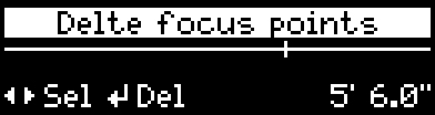
Press the back button to go back.
¶ Flipping a Lens Table
If an axis map needs to be permanently reversed push the joystick to the right, then push the joystick to confirm.

If a map needs to be temporarily reversed we suggest to reverse the direction of the motor.
- Choose:
Menu > Motor direction
¶ Using an LDT-E Series Lens Data Encoder
Camera operators may wish to manually control the zoom (or other axis) instead of using a motor that feeds data to the MDR. A lens enoder can be used with a motor, or in replacement of, allowing the LDT-R2 to still gather the lens movement data.
DCS has its own brand lens data encoder called LDT-E Series. These are plug and play devices so there is no need to create a new or separate lens table when using them.
Note: the direction of the motor might need to be reversed: please go to the Changing the Motor Direction chapter.
A video tutorial explaining the set-up of the LDT-E1 can be found here
¶ Setting the axis for the Encoder
The LDT-E Series have a manual switch to set the axis to Focus, Iris or Zoom.
¶ How to calibrate the Lens Data Encoder
If using an LDT-R2/LDT-V Series without a Preston system:
- On the LDT-R2/LDT-V Series choose:
Menu > Calibrate LDT-E
If using an LDT-A2/LDT-M2 with a Preston system:
- On the LDT-A2/LDT-M2 press the blue button for 3 seconds
If using an LDT-R2/LDT-V Series with a Preston system:
- On the MDR3/MDR4 press the calibrate button
Then manually rotate the axis which is attached to the Lens Data Encoder from one end, pause for a second, then rotate to the other end. The LDT-E Series should now show as calibrated in the on-screen display.
¶ Changing the Motors direction
If for rigging purposes a lens motor or lens encoder need to be reversed:
- Choose:
Menu > Motor directionand selectReverseon one of the axes.

¶ Transferring Data between LDTs
Specific data can be shared between LDT-R2's and the LDT-V Series to save time and ensure consistency across multiple set-ups.
¶ Transferring Lens Tables
Lens tables can be shared between all LDTs with a Micro SD slot. Please note that lens tables made using the LDT-A2 and LDT-M2 on the ARRI LDA system are a different file format and cannot be shared to the LDT-R2/V Series (and vice versa).
The LDT-R2 saves individual lens tables as .XML files to the MicroSD card. If multiple LDT-R2s are being used, these lens tables can be shared between devices.
-
Insert the MicroSD Card with the lens tables on into a computer,
-
Copy the .XML files from the "LENSES" folder onto the hardrive,
-
Insert a formatted MicroSD card (how to format a MicroSD card for the LDT-R2),
-
Copy the .XML files to the "LENSES" folder on the new MicroSD card.
Backup the "LENSES" folder when any new lenses are added to the on the MicroSD card to avoid data loss in case of corruption.
¶ Transferring an LDT Configuration
All settings of a unit can be downloaded to the MicroSD card and uploaded to a different unit to mirror all settings.
Config files can only be shared between specic models. I.e. LDT-R2 config files will work with LDT-R2 units, but LDT-V1 config files will not work with LDT-V2 units.
When uploading config files to a unit all original settings of that unit will be lost. Either back-up the original config file or make a note of device specific settings such a network addresses and camera index.
To save the config file:
- Menu > Save Config
This will save a text file called 'Config' on the Micro SD. If a config file is already on the MicroSD it will overwrite it.
To share the config file with a different unit:
- Eject the MicroSD card from the original LDT-R2
- Insert the MicroSD card into the next LDT-R2
- Menu > Settings > Load Config
- Follow the on-screen instructions
¶ Lens Table Files Naming Convention
Each .XML file is named after the lens brand, focal length and last 3 digits of the serial number. Examples:
AOZ24987.XML
Angenieux Optimo Zoom 24-290mm sn.11218987
CVZ25324.XML
Cooke Varotal Zoom 25-250mm sn.5640324
ZU135767.XML
Zeiss UltraPrime 135mm sn.8185767
AS047211.XML
ARRI Signature Prime 47mm sn.9899211
¶ Lens Database
If the user decides to not use F-Map, the lens database can be organised as a list or as folders.
- List: LDT-R2 display.
- Folder: LDT-R2 creates a folder structure based on lens brand, type and a single file for each lens in the root of the MicroSD card.
¶ Shooting Tests
It is essential that a test is done for each workflow established on the show before shooting. The tests involve shooting with the LDTs set-up, followed by a round trip of the data where the metadata (however recorded) is married to the EXRs so it is available for vendors in post. This should be coordinated between VFX, Camera, the Lab, Pulls house and Vendors. The goal of these tests are to provide reassurance that all data will be accurate when recieved by vendors and to catch any issues in the pipeline.
DCS can be involved in any pipeline discussions either by attending an initial meeting or being looped into emails if additional support is required. Email info@dcs.film.
Below are the descriptions of how to do the camera portion of the tests.
Allow approximately one hour per camera type being used on the production.
¶ Injection Recording
The test will involve recording the metadata with a camera and recording a separate feed from the camera with an overlay to verify the data is correct at the final stage of the test. We recommend using a zoom lens (if any are being used during the shoot) in order to check all three axes.
¶ Internal Recording on Film Cameras
If the camera cannot be fed a timecode, such as with film cameras, it is essential to display a digislate or, at the very least, a timecode within every take. This ensures there is a reference to link the film with the lens data clip.
¶ Setting up the Test
- Encode a lens and test it (see Programming a New Lens Table),
¶ Shooting the Test
- Shoot test footage in camera and record separate overlay feed at the same time,
- At the time of pulls, data is merged into the EXR,
- Compare the metadata of the EXR file to the overlay footage.
¶ Internal Recording
Three tests are recommended and will involve recording a visual source of the data in the camera with the LDT-R2 recoding the metadata as a sidecar to verify the data is correct at the final stage of the test. DCS recommend using a different lenses for test one and two and a zoom lens specifically for the third racking test (if any are being used during the shoot) in order to check all three axes.
¶ Setting up the Tests
- Rig and set-up the camera and LDT as per the instructions in this manual,
- Encode a lens and test it (see Programming a New Lens Table),
- Ensure the LDTs Camera Index and Roll number match the current test mag:
- On the LDT-R2 Choose:
Menu > Settings > Camera IndexSet to T or what letter the test mags are labelled with,
Menu > Settings > Rolland set to the current test mag
It is very important that the clip number of the camera mag and LDT clip number match at all times. Do not run the camera without the LDT attached.
For Each test a written visual representation of the FIZ values is required, for instance a clapper board with the lens values written on it.
¶ Test One - Static Test (Prime or Zoom)
- Set each axis to a value e.g. T-Stop 4, Focal length 22mm, Focus distance 6ft,
- Write on the board the test number, the lens name, and the values of each axis,
- Record a 10 second clip
¶ Test Two - Static Test (Different Prime or Zoom)
- Set each axis to a different value than test one e.g. T-Stop 5.6, Focal length 45mm, Focus Distance 30ft,
- Write on the board the test number, the lens name, and the values of each axis,
- Record a 10 second clip
¶ Test Three - Racking Test (Zoom Lens)
- Set each axis to a value e.g. T-Stop 4, Focal length 22mm, Focus Distance 6ft,
- Write on the board the test number, the lens name, the static values of each axis, and the range of the span of each axis (e.g. Iris T1.8 - T22, Focus 16"-Inf, Zoom 15mm - 30mm)
- Record a clip,
- During the recording, rack each axis one at a time, starting at the static number rotating the axis from one end to the other and returning to the static number.
After completing the tests remember to set the Camera Index on the LDT-R2 back to the corresponding camera letter.
¶ Processing the Tests
- The camera mags should be sent to lab with the microSD sidecar files from the LDT,
- During the VFX pulls proces, merge the CSV files to the EXR,
- Compare the metadata of the EXR file to the data in the test footage - this should be verified by a VFX vendor.
Please be aware that the extreme values in the CSV/EXR during the racking test may exceed the values in the image slightly. Most lenses have hard stops that go further than the values written on the lens. This is normal and should only flag an issue if the values far exceed the values displayed on screen.