As of April 2024 all lens tables must be built on the LDT-R2. Tables for the LDT-A2 and LDT-M2 can be exported from the LDT-R2 unit and no longer need to be built using the Arri LDA system.
If you have rented the LDT-A2 or LDT-M2 and were not provided with an LDT-R2 (or similar) to build lens tables, please contact your rental house.
An LDT-R2 is required to make lens tables. Contact the rental house if you have not been provided one.
¶ Introduction
DCS’ LDT-A2 is a lens encoding system for the Arri ALEXA family. It reads the Focus, Iris and Zoom motor movements and translates this information into compatible data for the host camera. This metadata is then written directly into the ArriRaw camera files in real time.
LDT-A2 Compatibility:
- Preston MDR-3/MDR-4/MDR-5
- Preston HU3/HU4
- ALEXA SXT, LF, 65
Please contact DCS for more information if your device is not listed here.
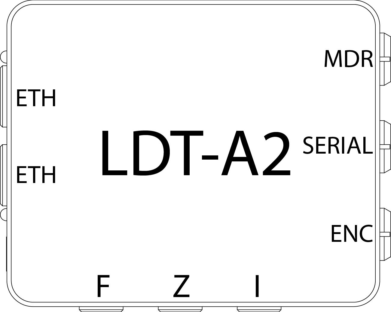
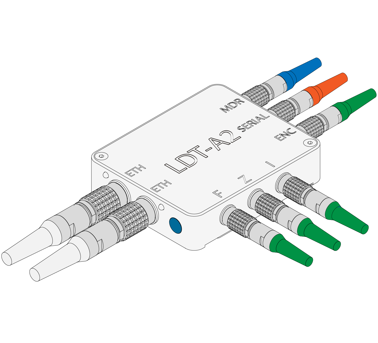
¶ LDT-A2 Components
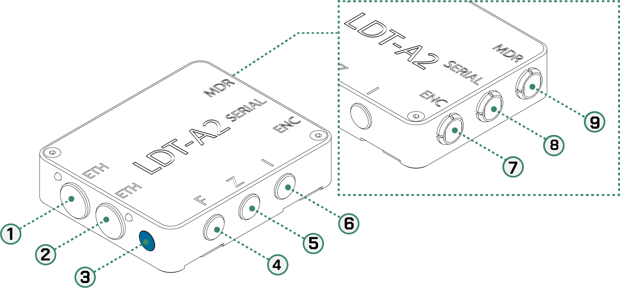
| 1 | ETH | 10-pin 1B Lemo | 4 | F | 5-pin 0B Lemo | 7 | ENC | 6-pin 0B Lemo |
| 2 | ETH | 10-pin 1B Lemo | 5 | Z | 5-pin 1B Lemo | 8 | SERIAL | 4-pin 0B Lemo |
| 3 | ENC CAL | LDT-E Calibration Button | 6 | I | 5-pin 0B Lemo | 9 | MDR | 4-pin 0B Lemo |
¶ Physical Connections
| Name | Type | Description | Cable Codes |
|---|---|---|---|
| ETH | 10-pin 1B Lemo | Camera Ethernet / Loop out | ETH / ETHA |
| ETH | 10-pin 1B Lemo | Camera Ethernet / Loop out | ETH / ETHA |
| SERIAL | 4-pin 0B Lemo | Serial passthrough connection port | CT |
| MDR | 4-pin 0B Lemo | Preston MDR Serial connection port | MDR, MDRP |
| F | 5-pin 0B Lemo | Alexa CLM Focus connection port | FIZA |
| I | 5-pin 0B Lemo | Alexa CLM Focus connection port | FIZA |
| Z | 5-pin 0B Lemo | Alexa CLM Focus connection port | FIZA |
| ENC | 6-pin 0B Lemo | Lens data encoder connection port for LDT-E1 | ENC |
¶ Cable Types and Codes
All DCS cables are categorized using a code and a bend relief color for each of the cable types. Cables have two default lengths, 12, 18 or 24 inches and the connector type can be straight (S), right angle (R), or anglissimo (O). Custom cables can be made upon request.
| Code | Bend Relief Color | Type Port Name |
Description |
|---|---|---|---|
| ETHA | Black | 10-Pin 1B Lemo to RJ-45 RCU |
ETHA cable connects the LDT-A2 to a computer for lens table creation and firmware updating. |
| ETH | White | 10-Pin 1B Lemo to 10-pin 1B Lemo CAM |
ETH cable connects LDT-A2 to the ethernet port of the Alexa camera. |
| CT | Orange | 4-pin 0B Lemo to 6-pin 1B Lemo SERIAL |
CT cable connects the Preston MDR3/MDR4 serial port with a CineTape. This cable connects to the LDT-A2 Serial connector if the Preston MDR serial ports are in use. |
| MDR | Blue | 4-pin 0B Lemo to 4-pin 0B Lemo MDR |
MDR cable connects the LDT-A2 to a Preston MDR3/MDR4 serial port. |
| MDRP | Blue | 4-pin 0B Lemo to 4-pin 0B Lemo MDR |
MDRP cable connects the LDT-A2 to a Preston MDR3/MDR4 serial port. Also provides power. |
| FIZA | Green | 5-pin 0B Lemo to 12-pin S103 Fischer F, I & Z |
FIZ cable connects the LDT-A2 to the focus, zoom and iris CLM ports of the Alexa camera. It injects the encoded data into the RAW file. |
| ENC | Green | 6-pin 0B Lemo to 6-pin 0B Lemo ENC |
ENC cable connects the LDT-E1 to the LDT-A2. Look at Using a Lens Data Encoder |
¶ Updating the LDT-A2 Firmware
The LDT-A2 should come up-to-date with the most recent firmware. If you need to check the firmware or update for some reason please get in contact with where you rented the LDT or DCS.
If you are from a rental house and are looking for firmware update information this can be found in the LDT-Tester manual on the rental house support site here.
¶ Lens Mapping
Full guide for lens mapping can be found here: Lens Mapping Guide
Creating accurate map files for each lens is vital when using the LDT.
Lens maps must be created on the provided LDT-R2 unit.
The lens files will then be converted for use with the ALEXA camera and imported into the body via the SD cards’s LDA folder.
If lens maps have already been created and imported, then skip this section.
A step-by-step mapping guide can be followed to ensure that maps are built correctly.
If the equipment supplier did not provide an LDT-R2, please contact the appropriate rental house, where you can obtain an LDT-R2 mapping unit at no extra charge.
¶ Setting up the Preston
Setup the Focus / Iris / Zoom direction for natural use on the Preston. If you are using a separate iris or zoom handset, then connect this now and ensure the direction of the preston motors are correct.
Lens tables must be be made using a Preston MDR3 running the latest firmware. Please update your MDR 3 first. An MDR4 can be used for operation once tables have been built - please contact DCS support for more information and supported firmware versions.
In order to correctly create lens maps on the LDT-R2 unit, Preston F-Mapping should be disabled. This can be enabled for normal operation once the lens tables have been made but it is essential it’s disabled when creating the lens tables.
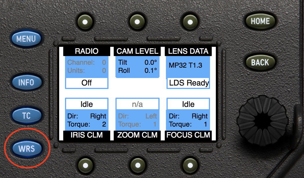
¶ Setting up the Arri Alexa
Press the WRS button to go to the WRS screen. From here, all camera settings related to the Wireless Remote System can be accessed.
- Choose
WRS > Lens data > Options > LDS mount > Off - Set
Lens distance unitto the measurement units required.
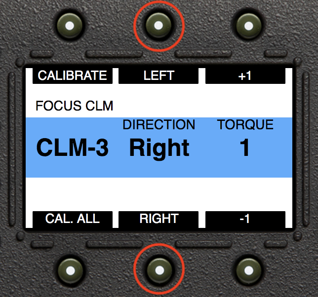
¶ Camera Axis CLM Direction
The direction of each axis must be set to RIGHT on the camera, in order to maintain the way the map was built on the LDT-R2. If rigging a different way to the map, this option can be changed were appropriate.
- Choose
WRS > Focus CLMand set the direction to RIGHT - Choose
WRS > Iris CLMand the direction to RIGHT - Choose
WRS > Zoom CLMand the direction to RIGHT
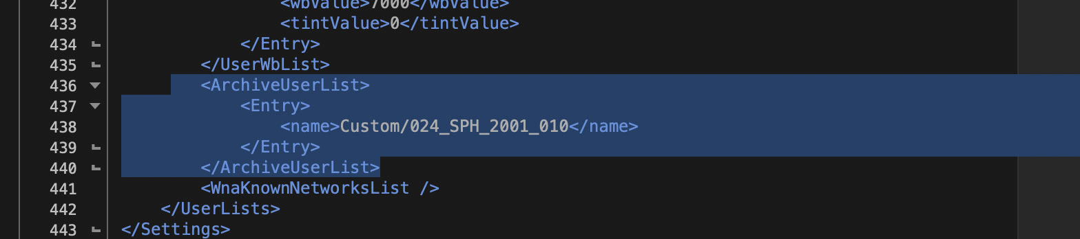
¶ Camera - Load User Setup
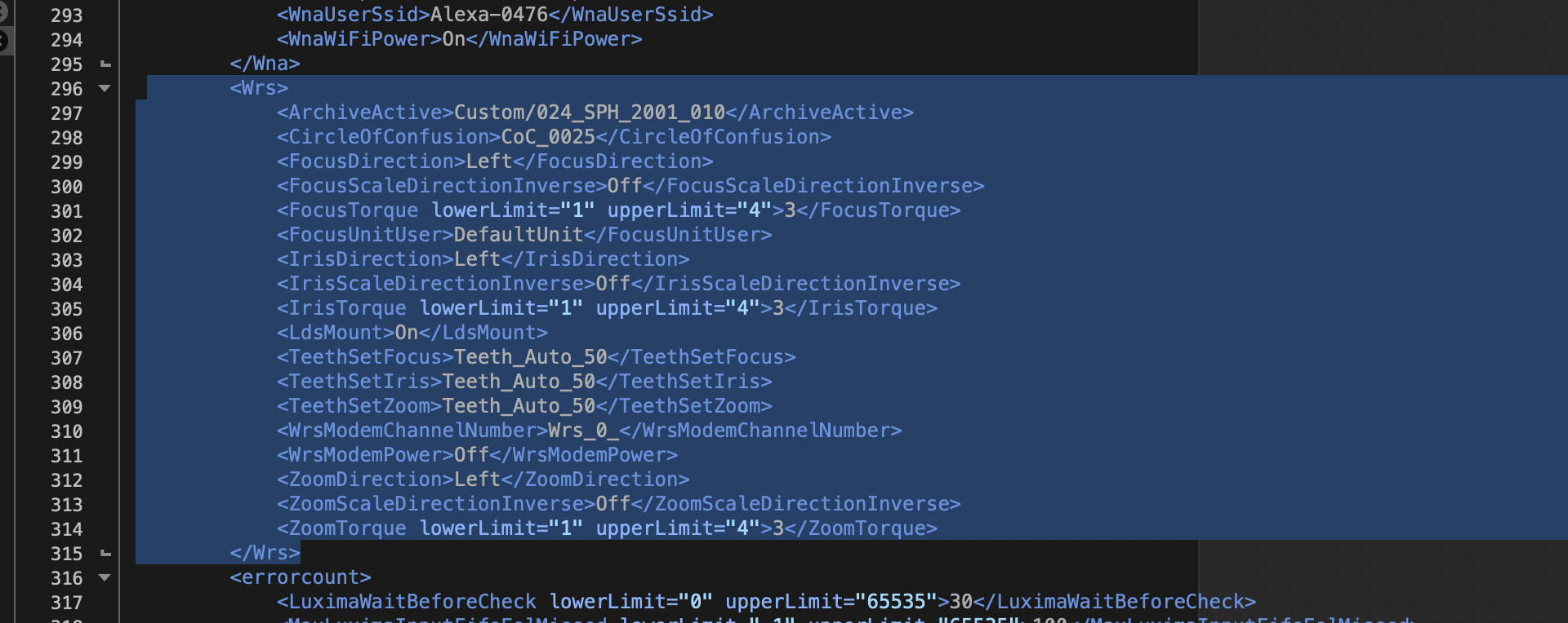
If loading a user setup on the camera, it is essential to edit the XML setup file to remove specific lines. This step ensures that critical files and settings related to the LDT remain unchanged by the User Setup.
To do this:
- Remove all content including and between <ArchiveUserList> and <ArchiveUserList>,
- Remove all content including and between <Wrs> and <Wrs>.
For reference, examples of the lines to remove are shown here:
- Example of 'ArchiveUserList' lines to delete:
- Example of 'Wrs' lines to delete:
After making these changes, users can safely load the User Setup onto the camera as usual.
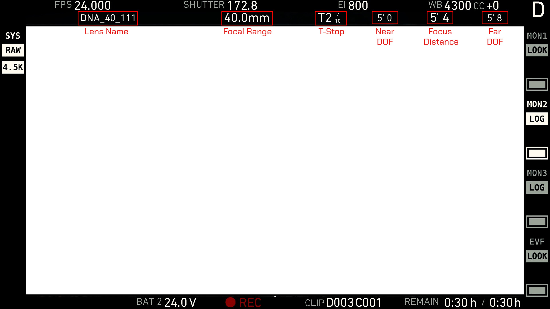
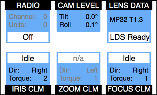
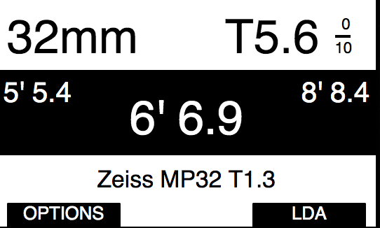
¶ Overlay Lens Data on monitor
In order to display lens data as an overlay on an SDI monitor, do the following.
- Choose
MENU > Monitoring > MON OUT 1/2/3 > Frame Lines + Status Info > LDS Info > On
¶ Overlay Guide
¶ ALEXA LF
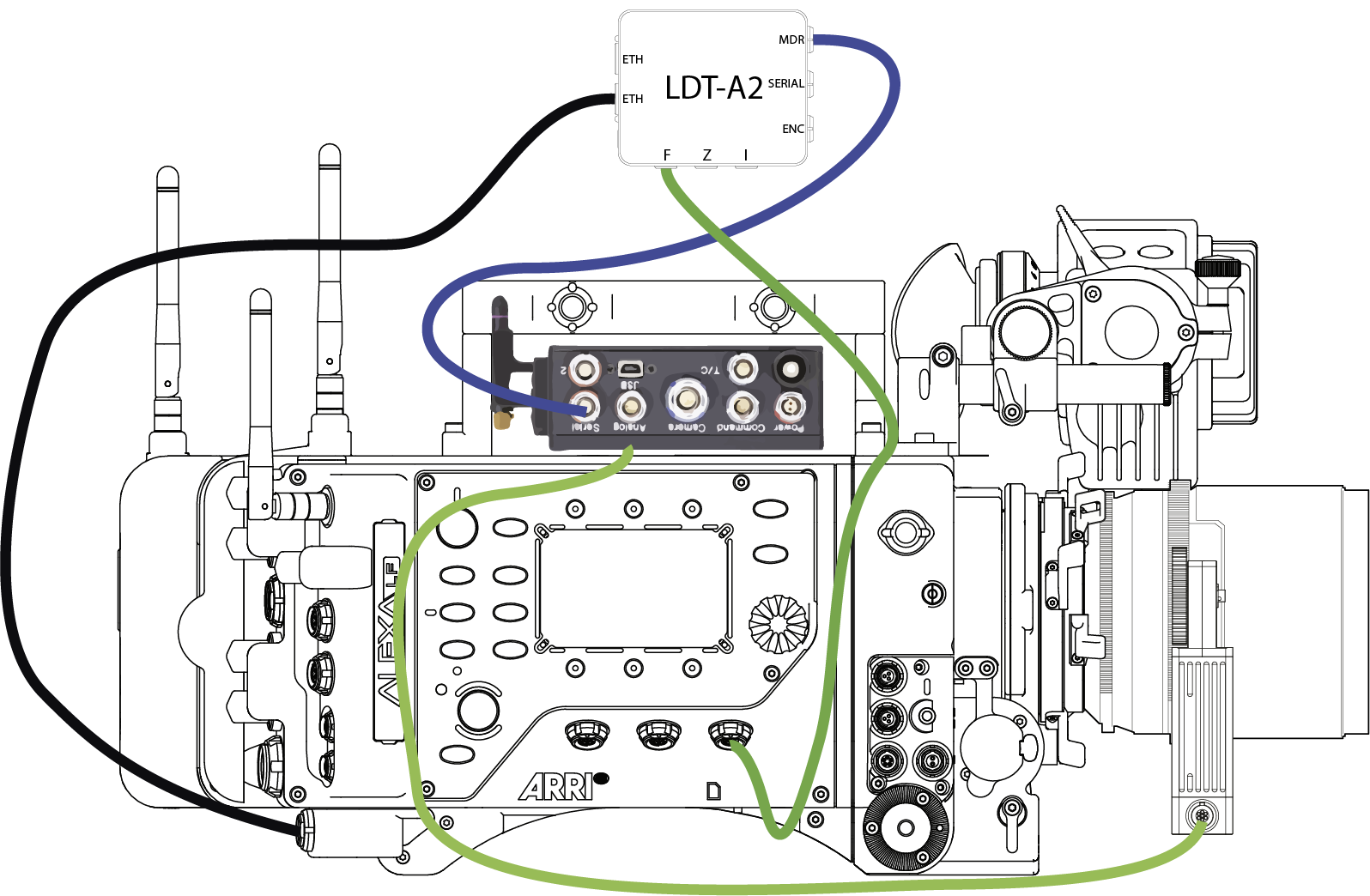
¶ Rigging the camera
- Connect the LDT-A2 using the MDRP Blue Cable from the MDR port on the LDT-A2 to the Serial port on the Preston MDR-3.
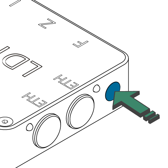
- Plug the ETH white cable from any of the ETH ports on the LDT-A2 to the Ethernet connector on the Alexa.
- Connect the green FIZ cables from the LDT-A2 to CLM Iris, Zoom and Focus ports on the side of the Alexa.
- Connect the Preston Hand unit to the MDR,.
- Press the calibration button on the Preston MDR. Visually check all active axes are calibrating.
Please note: this system requires that the MDR is always calibrated from the Preston. The button on the LDT-A2 is for calibration when only LDT-E encoders are being used.
¶ ALEXA LF Operation - Please Read
There is a known issue with the ALEXA LF and the LDT-A2, where calibration issues can occur.
Please ensure the following steps are followed everytime the camera is power cycled:
- Before powering the camera connect all equipment up as per normal operation,
- Power the camera,
- Once everything has started up fully, disconnect the FIZA cables from the camera,
- Reconnect the FIZA cables to the camera.
This should be integrated into the daily workflow of the camera, and if done so will avoid any calibration issues.
If there are any issues relating to this, or anything else please contact DCS support on support@dcs.film.
¶ If Other Devices Require the Camera Ethernet Port
If the Ethernet port of the Alexa is needed for another device, the LDT-A2 has two ETH ports which will loop through information. For instance, if the show requires use of the Arri RCU4, connect the Ethernet cable from that device to the spare ETH port of the LDT-A2 and this will connect to the camera. Both ports on the LDT-A2 can be used in this way.
¶ Using a Lens Data Encoder
Camera operators may wish to manually control the zoom instead of using a motor. A lens enoder can be used instead of a motor allowing the axis to spin freely whilst still providing the LDT-A2 with zoom data.
DCS provides a lens data encoder called LDT-E1. This device is plug and play, and does not require additional or separate lens tables to work.
A video tutorial explaining the set-up of the LDT-E1 can be found here
To use the LDT-E1:
Rig the LDT-E1 to the zoom axis,
Select “z” on the LDT-E1 using the physical button,
Connect the ENC cable to the port of the LDT-E1 and the ENC port of the LDT-A2.
The LDT-E1 can also be used to send focus or iris data to the LDT-A2 if required. Simply rig the encoder on the desired axis and change the physical button to that axis.
Note: the direction of the motor might need to be reversed: please go to the Changing the Motor Direction chapter.
¶ Setting the axis for the LDT-E Series
Select an axis using the switch on the LDT-E.
For example:
- Rig the LDT-E to the zoom axis,
- Connect the LDT-A2 and the LDT-E using the ENC cable.
- Select z on the LDT-E using the physical button,
The LDT-E can also be used to send focus or iris data to the LDT-A2 if required. Simply rig the encoder on the desired axis and change the physical button to that axis.
If Using an LDT-E with a Preston system press the calibrate button on the Preston MDR then rotate the desired axis from one extreme to the other pausing for one second at each end.
¶ Using Multiple LDT-E Series Encoders
The LDT-E1 can be daisy chanined with additional LDT-E2 encoders to deliver all lens axis data to an LDT-M2.
¶ Calibrating Only LDT-E Encoders
If solely using LDT-E series encoders with no Preston system, calibration is done by
- holding down the blue button on the LDT-M2 for 3 seconds,
- manually rotating each axis from end to end.
¶ Changing the Motors direction
If for rigging purpose a lens table needs to be reversed:
- Choose
WRS select the desired axis and change to Right or Left
¶ Serial Loop Through for 3rd Party Devices
The LDT-A2 is equipped with a serial port that works as a passthrough for several devices. This is benifical for when an MDR does not have a spare serial port. Users intending to utilise this port should conduct comprehensive testing of the entire setup and connected devices to preemptively address any potential compatibility issues.
¶ Using a Light Ranger with the LDT-A2
It is recommended that the Light Ranger is used through the serial port of the Preston MDR-3 or MDR-5.
If the LDT's serial pass-through is required, then please get in touch with DCS.
- Email: info@dcs.film
- Phone: +44 (0) 20 8895 6592
DCS would encourage that this setup is fully tested before production begins, to detect any compatibility issues with the user’s setup.
¶ Selecting a Lens Table
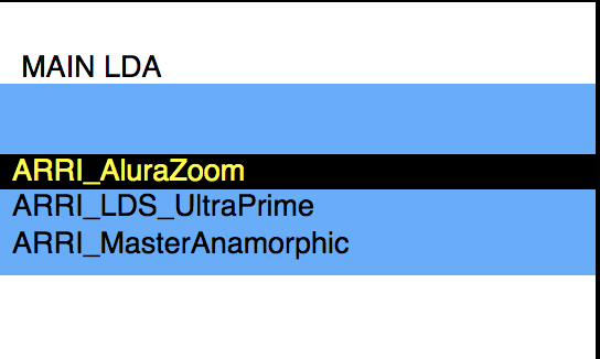
The lens tables are recalled through the GUI of the camera:
- Choose
WRS > Lens data > LDA > Add> Add+Use
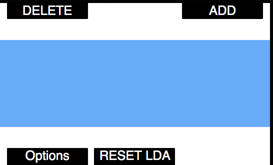
- Calibrate the lens by pressing calibrate on the Preston MDR.
¶ Testing the Lens Tables
Load the relative LDA Map from the WRS Menu
- Check lens lines up on the Lens Data page.
We suggest checking at least three random points to make sure it lines up.
¶ Shooting a Test
When shooting test footage, allow approximately one hour per camera type being used on the production. A test will involve recording the metadata with a camera and recording a separate feed from the camera with an overlay to verify the data is correct at the final stage of the test. We recommend using a zoom lens (if any are being used during the shoot) in order to check all three axes.
- Rig and set-up the camera and LDT as per the instructions in this manual,
Do not run the camera without the LDT attached.
For Each test a written visual representation of the FIZ values is required, for instance a clapper board with the lens values written on it.
¶ Test One - Static Test (Prime or Zoom)
- Set each axis to a value e.g. T-Stop 4, Focal length 22mm, Focus distance 6ft,
- Write on the board the test number, the lens name, and the values of each axis,
- Record a 10 second clip
¶ Test Two - Static Test (Different Prime or Zoom)
- Set each axis to a different value than test one e.g. T-Stop 5.6, Focal length 45mm, Focus Distance 30ft,
- Write on the board the test number, the lens name, and the values of each axis,
- Record a 10 second clip
¶ Test Three - Racking Test (Zoom Lens)
- Set each axis to a value e.g. T-Stop 4, Focal length 22mm, Focus Distance 6ft,
- Write on the board the test number, the lens name, the static values of each axis, and the range of the span of each axis (e.g. Iris T1.8 - T22, Focus 16"-Inf, Zoom 15mm - 30mm)
- Record a clip,
- During the recording, rack each axis one at a time, starting at the static number rotating the axis from one end to the other and returning to the static number.
¶ Final Steps
- Extract the lens medatada from the ARRIRAW (see Appendix 3: Extracting data from ARRIRAW footage),
- Merge the extracted CSV files to the EXR,
- Compare the metadata of the EXR file to the overlay footage.
¶ Lens Link Support
The LDT-A2 is compatible with the Lens Link workflow to enable motor control at a greater range.
This setup requires the DCS Bridge.
The DCS Bridge does not have passthrough for other devices such as CineRT or Light Ranger.
- Connect the DCS Bridge's EXT port to the LDT-A2's serial port using the blue booted MDRP cable,
- Power the DCS Bridge with the PWRG or PWRH cable.
For further guidance on this workflow, please refer to the Lens Link Manual.