| Plugin Version 2.7 | 01/05/2024 |
¶ Introduction
The DCS Plugin for Unreal Engine has been developed to provide real-world focus, iris and zoom data for digital cameras, utilising data from the LDT units. This guide will walk users through the setup and use of the plugin.
This guide is related to the Unreal Engine 5 DCS Plugin.
For the Unreal Engine 4 DCS Plugin walkthrough, see here.
¶ Hardware
The following kit is compatible with the DCS Plugin:
¶ LDT Units
Analogue and smart lens data data streaming and recording.
Wireless receiver unit for LDT Data.
Smart lens only data streaming.
¶ Lens Control Compatibility
A compatible lens control system must be used in order to provide the LDT with accurate data.
Alternatively, the LDT-E Series can be used to track the movement of the lens, allowing for accurate data even without a lens control system.
Smart lenses with a Cooke /i port can be used to stream data without any motors being required.
¶ LDT-V2
- Preston MDR3/MDR4
- Preston HU3
- Preston HU4
- Arri cforce - via LCUBE
- Cmotion cPRO - via LCUBE
- Cmotion Camin One - via LCUBE
- Cmotion DXL2 Module
- Cmotion Camin 3
- Tilta Nucleus-M
- Smart Lenses with Cooke /i port
- LDT-E Series
¶ LDT-TX1
- Smart Lenses
Smart lenses must have a Cooke /i port for connections.
If the lens has Zeiss XD data, then shading and distortion data can also be utilised.
¶ LDT-V2 Unit Setup
A rigging guide for the LDT-V Series can be found here.
If using multiple LDT-E1/LDT-E2 units, ensure they are set to a different axes via the switch near the bottom of the unit.
Any mode can be used for streaming, allowing the recording of metadata as per normal LDT use. 'Virtual Production' mode is intended for use when users are solely streaming data.
¶ Wired Connection (LDT-V1/LDT-V2 Settings)
These settings must be set correctly for the wired workflow to be enabled.
- Choose:
Menu > Settings > Network > DCS streaming > Service > On Menu > Settings > Network > Remote IP >Set to the IP of the target machine,Menu > Settings > Network > Remote Port >The default DCS port is 33322.Menu > Settings > Network > Local IP >User defined (change if the DCS Unreal Engine Plugin is set to something different or there is other traffic on this port),Menu > Settings > Network > Router IP >User defined,Menu > Settings > Network > Netmask >User defined,
¶ Wireless Streaming (LDT-V2 Only)
Menu > Frequency
Set this value to the same frequency that the LDT-RX1 is running.
Network settings selected on the LDT-V2 will not be used if connected to the LDT-RX1. The LDT-RX1 settings take priority and will be utilised.
Quickstart Guide:
¶ LDT-RX1 and LDT-TX1
A comprehensive guide to the settings of the LDT-RX1 and LDT-TX1 can be found here.
The LDT-RX1 must be used to enable the wireless capabilities.
The LDT-TX1 is intended only for use with smart lenses.
Ensure an antenna is attached on all LDT units for wireless use.
Quickstart Guides:
¶ Creating Lens Maps (LDT-V Series)
Lens maps are an essential part of the LDT process. They must be created on the same lens control system that the user will be working with.
Please ensure all units and lens control devices are on the latest firmware.
LDT lens maps are not contingent on 3rd party lens maps. The LDT-E Series can be used in place of Preston motors.
Smart lenses are an exception to this as the LDT has access to the full map provided by the lens connection. No maps will have to be made for smart lenses.
A full guide for lens mapping can be found here: Lens Mapping Guide
¶ Programming Lens Tables on the LDT-V series
Creating lens tables is only required with the Preston, LDT-E1/LDT-E2, Arri LCUBE and the Tilta Nucleus-M.
Smart lenses with an /i port and Cmotion send encoded data, so no lens tables are required.
Creating a lens table is essential to ensure the streaming process. To do this, the relevant lens information (lens name, brand, serial number etc.) should be entered into the LDT-V series, along with all of the values for each axis (focus, iris, zoom) for each lens.
Detailed instructions on how to do this can be found in the LDT-R2/LDT-V1 Manual.
¶ DCS Emulator
The LDT Emulator is intended to assist with checking the users Unreal Engine project is set up to be compatible with either the LDT-V2 or the LDT-TX1.
The application sends simulated lens data into the DCS Plugin for Unreal Engine. The lens data is the same format that originates from DCS’ LDT devices and can be used to test and troubleshoot with or without the LDT hardware.
The full LDT Emulator guide can be found here.
¶ Emulator Download
¶ DCS Unreal Engine Plugin Guide
The following sections are computer-related.
This section will cover installing the DCS Plugin for the correct UE version.
The DCS Plugin must be copied to the following location:
C:/Program Files/Epic Games/EU_5.4/Engine/Plugins.
This is done automatically when installed via the Epic Marketplace.
¶ Installing the Plugin
- Open the Unreal Engine Launcher and access the "Marketplace" tab.

- Search for the “DCS Plugin” and select the listing created by DCS.

- Select the "DCS Plugin".
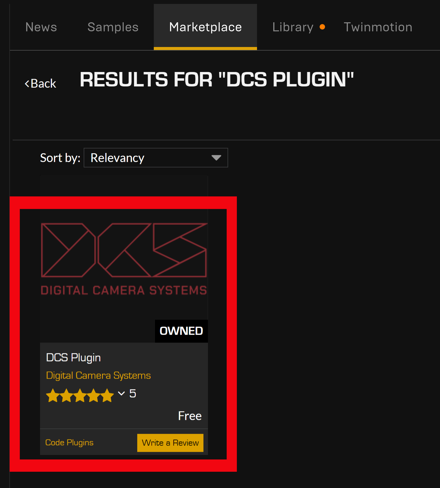
If prompted with “Free” and “Add to Cart” buttons, select the “Free” button. This will add it to your library.
- Click on "Install to Engine". In the drop-down menu, select the Unreal Engine Version that your project is running. Select "Install" on the desired version and the download will begin.
The progress of the download can be viewed in the downloads tab on the left.
The "Install to Engine" option can be used again to download any other version already installed on the users machine.
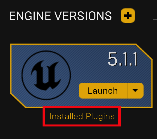
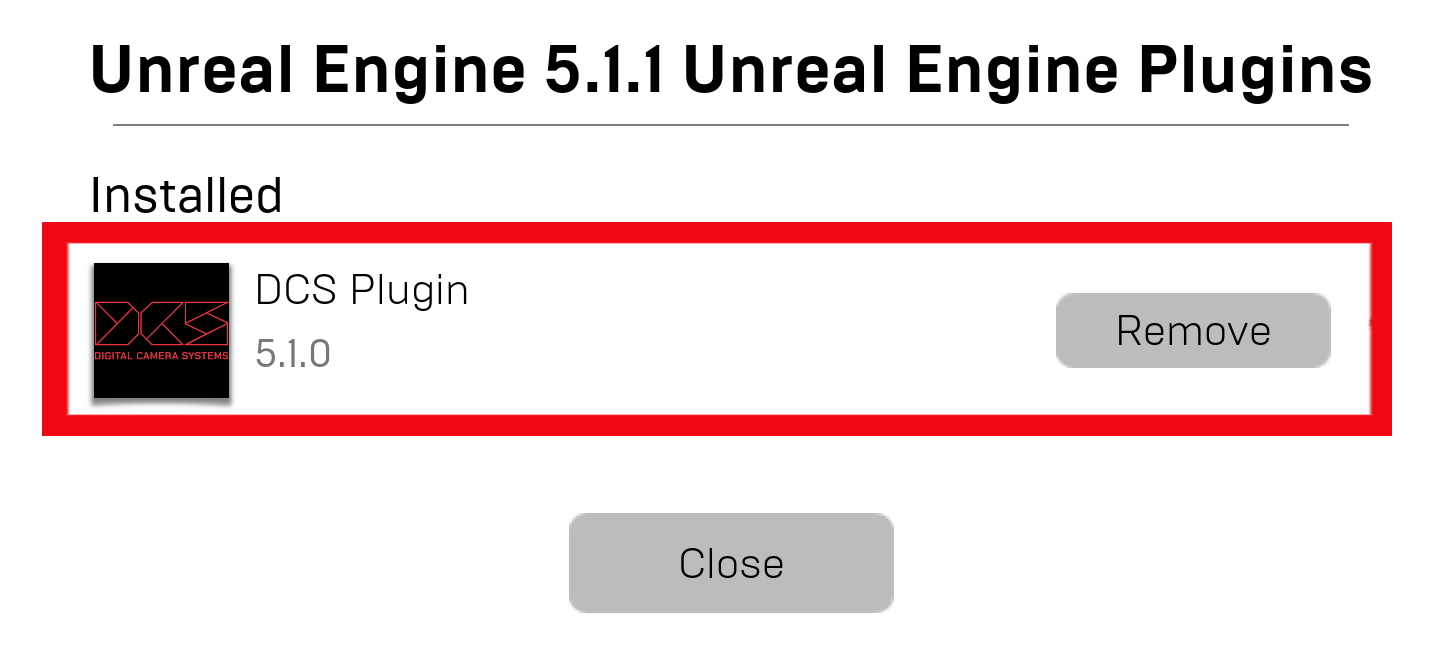
- When the download is complete, users can verify that the DCS Plugin has been installed by going to the library and clicking on “Installed Plugins” underneath their intended Engine version.
¶ DCS Plugin - Project Guide
The following is a guide to setting up the DCS Plugin inside the UE project.
¶ Setting up the Plugin
-
Once the Plugin has been installed, users can launch their project on that Engine version.
-
To activate the DCS Plugin, navigate to “Edit > Plugins”.

- Open the “Window” menu and activate “Virtual Production > Live Link”.
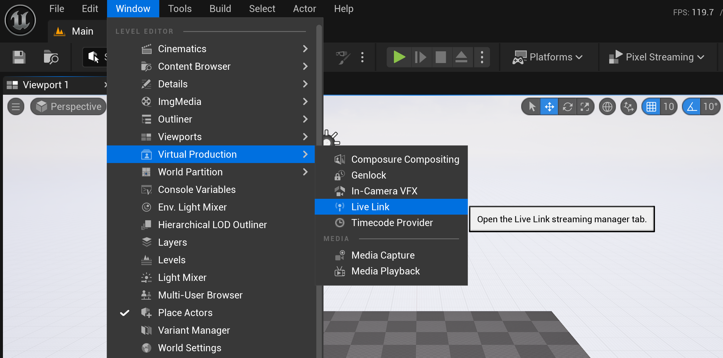
Check that the tabs have appeared on the main display.
-
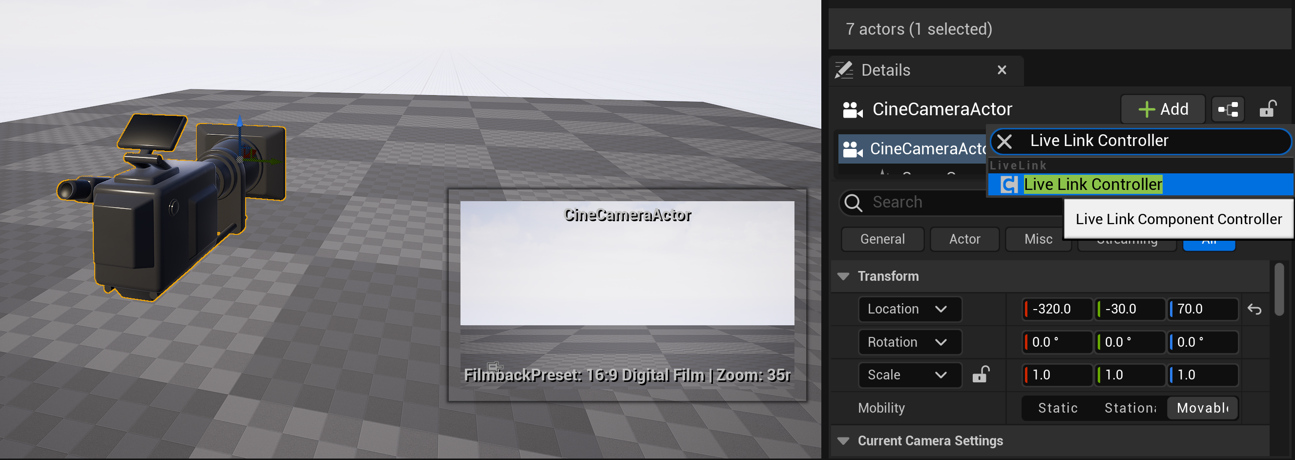
Place a "CineCameraActor" into the scene via the desired method, such as the "Place Actors" menu.
-
With the desired CineCameraActor selected, select the “Add” button.
Search for “Live Link Controller” in the drop-down menu and to apply it.
¶ Connecting a Cine Camera Actor with a DCS Live Link Device
- In the Live Link window, select 'Add Source > DCS Plugin Source'.
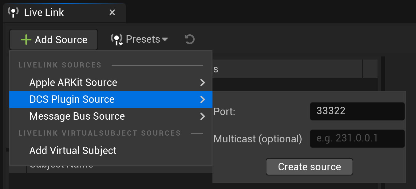
- Choose 'Create source'. The DCS Live Link Settings window will be created.
If using multicast then the address detail should be input first.
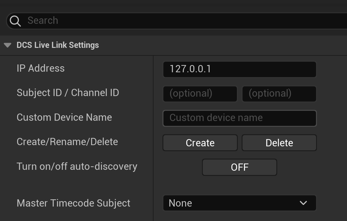
- With the new DCS source, on the 'DCS Live Link Settings' window, the IP Address of the LDT unit that is connected to the computer should be selected.
Enabling auto-discovery will input the correct values of a connected LDT.
If auto-discovery is off, then a device name must be chosen before the unit can be triggered.
Master Timecode can be set if enabled in the editor. Information on this optional step can be found here.
- The created subject can now be selected.
Green light means that there is an active connection with the LDT unit.
Yellow light means that there is currently no connected data.
- Open the Live Link Component on the CineCameraActor. Choose 'Subject Representation' and link it to the created LDT subject in the drop-down.
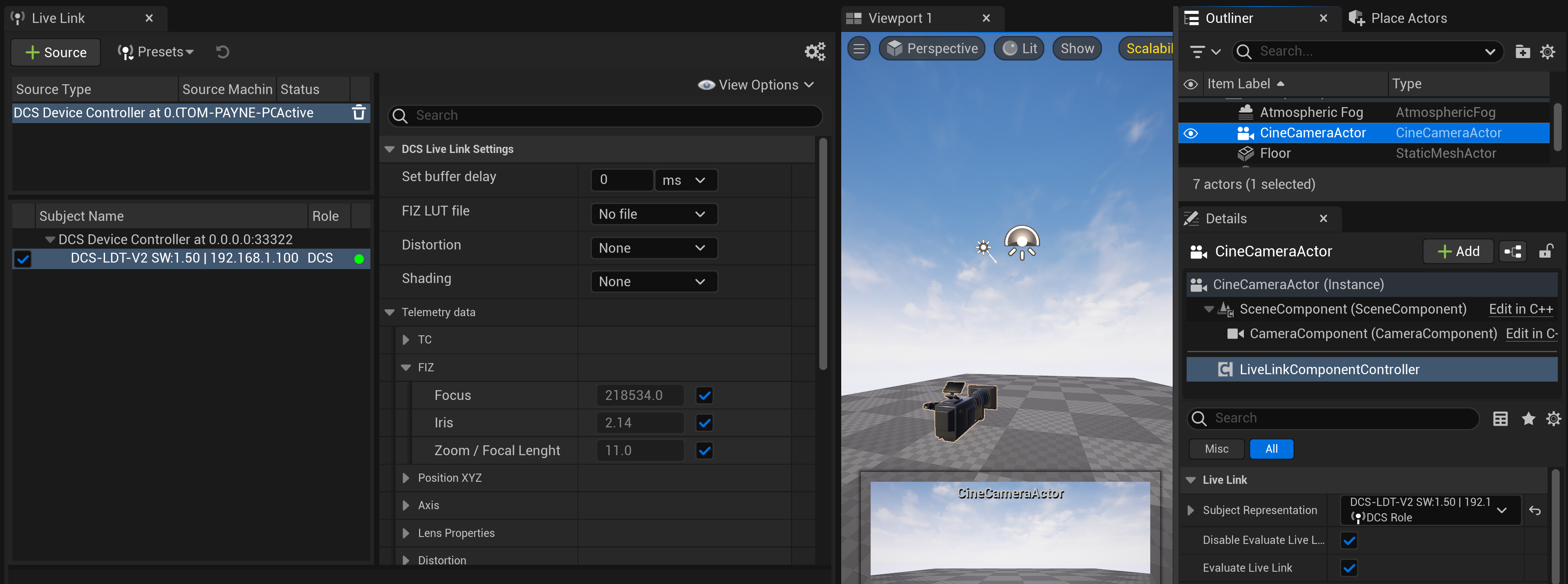
- Live Lens Data is now applied to that camera actor.
Data can be checked in the LiveLink FIZ tab.
If the FIZ tab data is '0', then check that a map is loaded on the LDT unit.
If the data in the DCS Live Link FIZ values is changing, but the camera preview is not updating, then ensure that the viewport is running in real-time and is not disabled.
¶ Lens Shading (Smart Lenses with Zeiss Xd only)
Shading data can be sent from a Smart Lens with Xd to the DCS Plugin via the LDT. If using this data there is an option in the plugin to to remove, or apply shading to the image.

¶ Applying Distortion (Smart Lenses with Zeiss Xd only)
The Plugin provides three options via the LiveLink tab.
- None
This disables any of the distortion data from being applied to the designated camera.
- Forward
This adds the lens distortion value to the Unreal Engine scene.
- Reverse
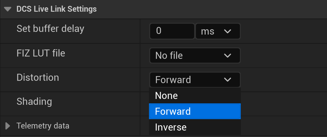
Reversing the distortion inverts the incoming values.
-
To enable this, select the desired camera actor and "Add" the "Lens" component.
-
Tick the "Apply Distortion" box to activate this feature.
-
In the LiveLink window, select an option under "Distortion" to apply the intended effect.
¶ Setup Completion
This concludes the core setup of the DCS Plugin's lens data workflow. All sections following this are optional and not required for normal use.
¶ DCS Live Link Detailed Interface Guide
¶ Source Creation Panel
This is where configuration is done to link the LDT hardware (or data emulator) to the DCS Plugin. In the "Live Link" window, click the “Source” button and select “DCS Plugin Source”. Settings can be left as the default values for this example (further explanation of these fields below). Press the “Create source” button.
Interface: The interface (e.g., ethernet) of the Host PC, which is connected to a network from which you want to receive data. Using “Any” receives data from all interfaces of the current PC.
Port: The default DCS port is 33322. In the instance of the port interfering with other network settings, this must be changed in the settings and on the LDT itself
Multicast: If using multicast enter the same multicast address that is being used on the LDT. If not using multicast leave blank. Multicast addresses start from 224.0.0.0 to 239.255.255.255.
¶ Source Settings
In the source settings it is possible to:
- add, rename, and delete DCS devices,
- turn on the auto-discovery feature to automatically find and connect devices (Note: if using the LDT Data Emulator, the auto-discovery feature will only work if the emulator sends the “Product Name” and “Product Brand” messages.),
- select the global timecode provider device.
Device IP Address: The LDT’s local IP address. This can be set locally in the LDT-V2 network menu when using the wired method. For Wireless with the LDT-RX1 or use of the LDT-TX1, the web browser settings can adjust this.
Custom Device Name: If adding a device manually, a custom name is required. The created device names will be in the following format: <custom_name>@<device_ip>. Note: There can be multiple devices with the same “Custom Device Name” but there can be only one device with the same Device IP Address. If trying to create a device with an already assigned IP Address, then it will rename that device instead.
Create DCS Subject:
● Create: Creates a device with a specific IP Address and Name
● Rename: Renames the device at the Device IP Address to the currently provided Custom Device Name
● Delete: Deletes a device at the Device IP Address. The Custom Device Name is not required.
Turn on/off auto-discovery:
● Manual: Manually add, rename, and delete devices
● Automatic: The plugin automatically detects DCS devices if they are sending data.
Master Timecode Device: If there are multiple devices added under the DCS Live Link Source, one can be selected as the global timecode.
¶ Select a Master Timecode Provider (Optional)
This setting is optional and not required for lens data to be accessed.
To select a DCS device as the Master Timecode Provider, select “Edit” > “Project Settings”.
Then search for “timecode”. Under the Timecode tab, select the "DcsTimecodeProvider" as the Timecode Provider
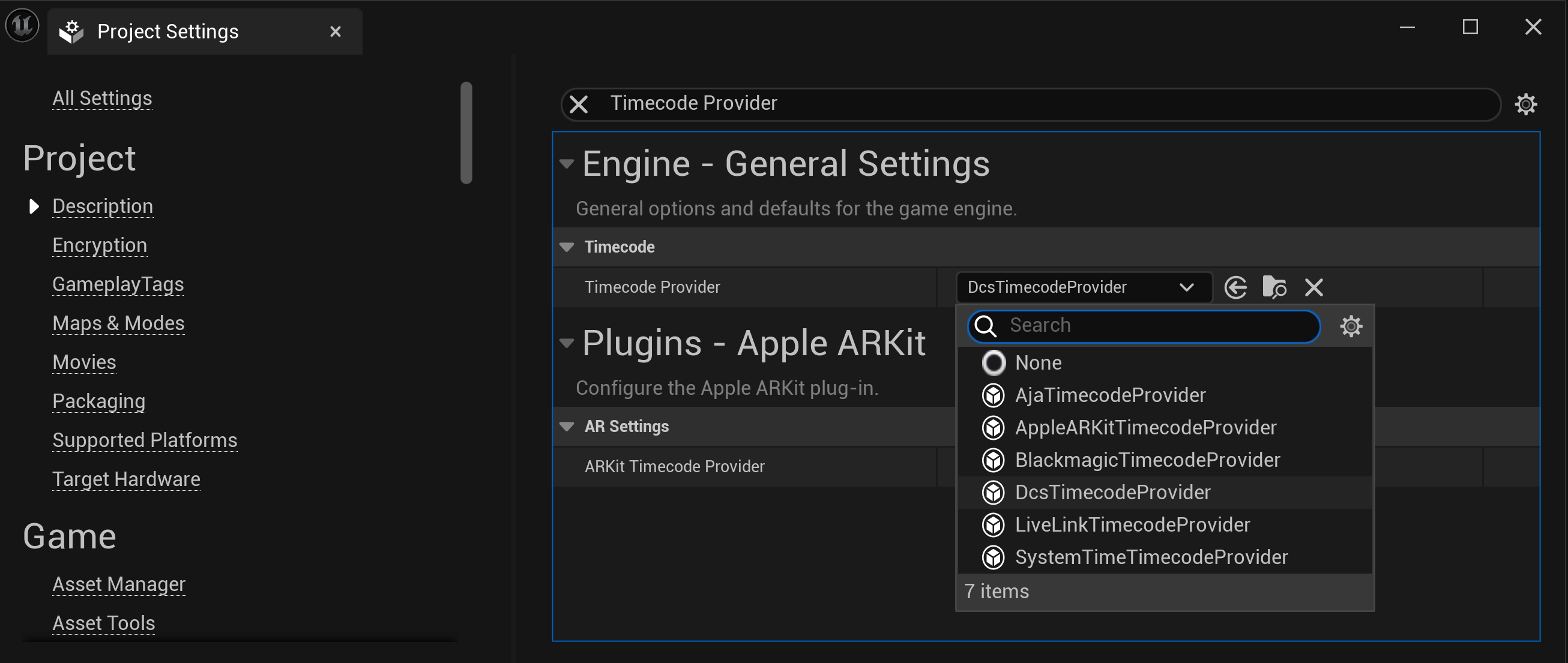
Once selected, the DCS device will be able to provide the global timecode for the project. The DCS Live Link Settings window will allow
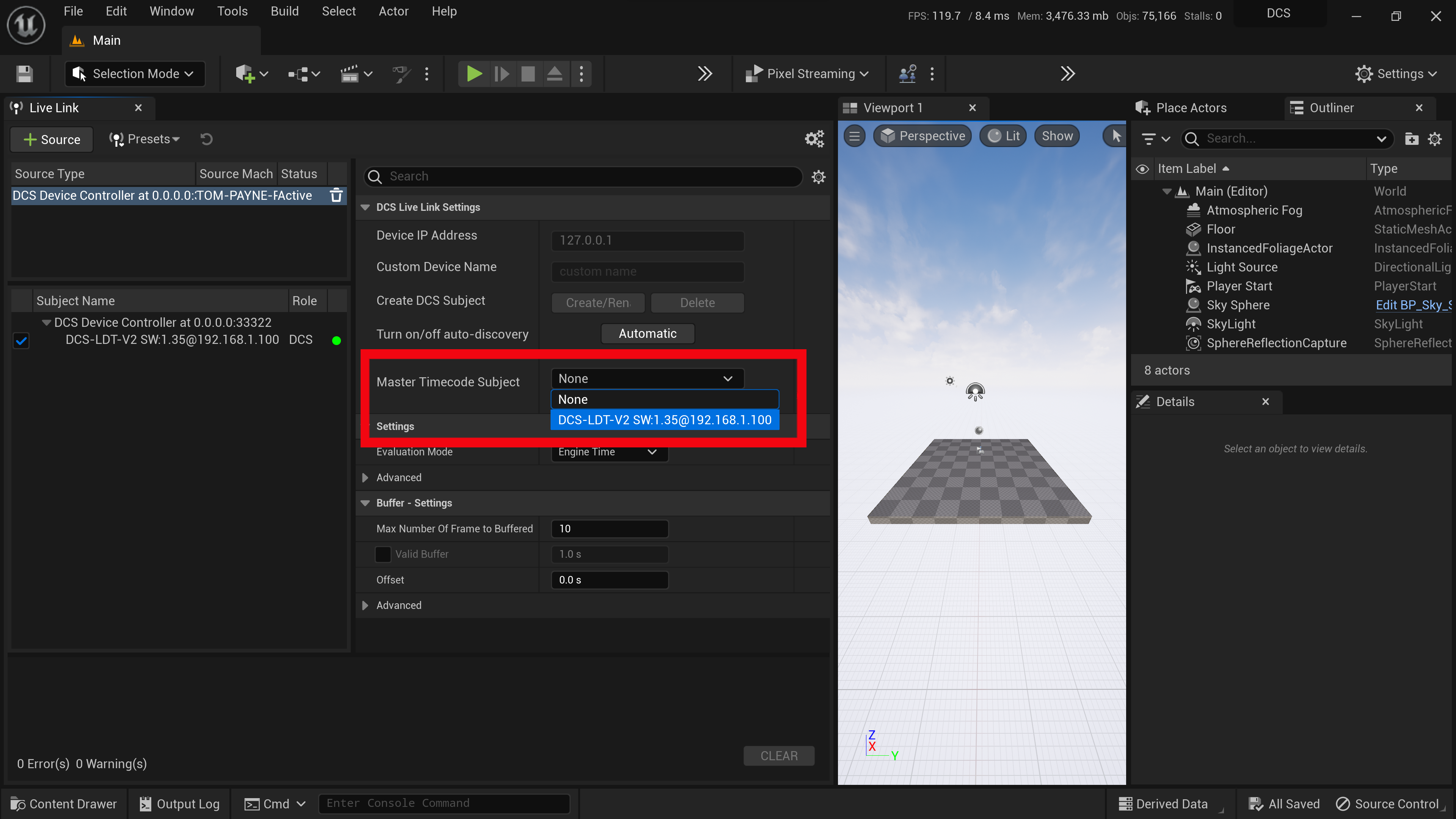
¶ Subject Settings
Set buffer delay: The Plugin can delay incoming data from LDT to match latency of other devices. Delay can be by milliseconds or by frames. A buffer will store the incoming data and release it after the specified delay:

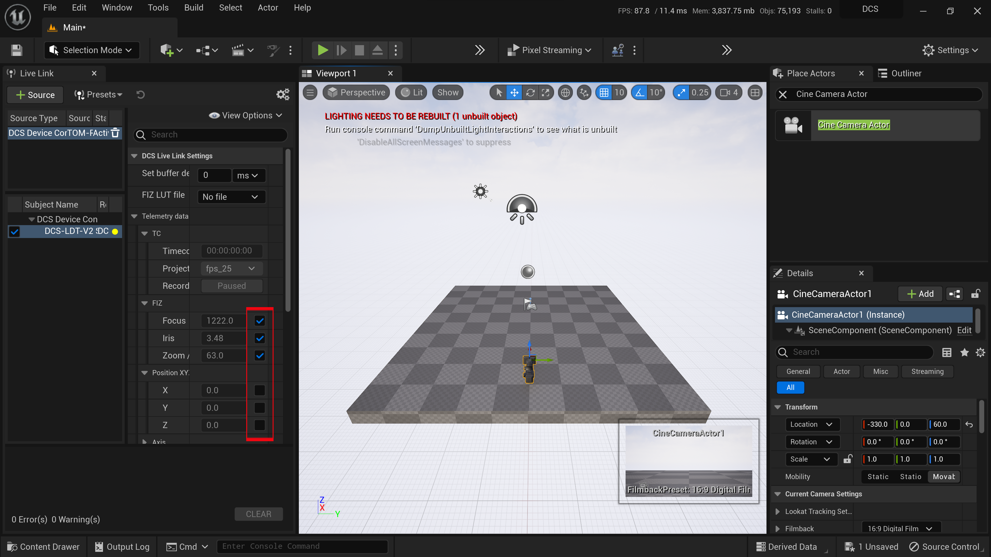
Telemetry data: Under the Telemetry data tab all possible data fields that the hardware or the emulator can send can be seen. To specify which data is sent to the Cine Camera Actor enable that data by ticking the box or disable it by unticking the box. This feature is to assist if other 3rd party plugins are providing the same data as the LDT:
¶ DCS Live Link Component Features
The DCS Live Link Component is a Live Link Controller with extended functionality. If a DCS Live Link Subject is connected to the DCS Live Link Component some of the extended functionality is available under the DCS Live Link Role settings.
¶ Exposure Compensation (Optional)
The first feature under the DCS Role is the option to automatically adjust the exposure of the Unreal Engine scene based on the movement of the iris of a real-world lens.
The LiveLink Controller once linked to an LDT, will enable exposure settings to be automatically adjusted by the incoming lens data. The iris axis of the real lens will be taken into account.
By default, the Exposure Compensation Type is Locked. This means there isn’t any compensation happening.
- Exposure Compensation types:
● Locked: The camera’s aperture won’t affect the scene
● Sync: Based on the Exposure Compensation Zero constant that has been set, the compensation will be calculated and applied to the Camera Actor. By ticking Is Slave changes can be made to the direction of the calculation.
● Sync Outside a Range: When the aperture value is below the minimum, the exposure is calculated as in sync, with the minimum value as zero. The same method is applied when the value is over the maximum, just the zero value is equal to the maximum of the range. While the aperture is between the range the exposure compensation remains 1.
Note: With both “Sync” and “Sync Outside a Range” the constant values are measured in the same way as the aperture value.
¶ Using Blueprints
This is not a requirement of the DCS Plugin or lens data implementation.
A guide on the blueprint process can be found in the Unreal Engine 4 Guide. Setting up blueprints in UE5 follows a similar process, albeit with the engine's menu adjustments for UE5.
Full access lens data will already be accessible if the core set-up from this guide is followed. Blueprints are not a requirement. However, users can feel free to use blueprints to customise their workflow as they see fit.
We're currently in the process of updating this section. Should your project require blueprints and you would like assistance, feel free to reach out to DCS.
¶ Troubleshooting
¶ Network Troubleshooting
¶ Common Networking issues:
Ensure IGMP Snooping is disabled on all network switches.
If LDT-RX1 destination settings are changed, they may require a unit reboot in order for changes to fully take place.
¶ LDT-V Series Troubleshooting
Q: Data is stuck at 0 after the setup is complete.
A: A lens map must be selected for the linked FIZ data to be used.
Q: Data is present and linked, but the camera is not updating.
A: Ensure Unreal is set to Real-Time in the viewport.
¶ LDT-RX1 Troubleshooting
Q: Can I change the unit settings to match my network environment?
A: Yes, the LDT-RX1 settings can be changed from the browser menu. Some settings may require a unit reboot for changes to take effect. If the unit IP is altered, the browser will be accessed via this new address after rebooting.
Q: How do I pair LDT devices?
A: Check that the LDT-V2/LDT-TX1 and LDT-RX1 on the same frequency.
Q: How to I check that the units are linked when not currently on a data screen?
Is the light next to the LDT-RX1 antenna green? This means units are connected to the same frequency and are linked.
Q: How do I check that data is coming in on the LDT-RX1?
A: Check the 'Decoder' tab on the unit's web browser settings. Incoming data will be displayed on that screen. The LDT-V2/LDT-TX1 must have a lens loaded/connected for it to actively stream data.