| V3.0 | 22/07/2022 |
¶ Introduction
The DCS Unreal Engine plugin has been designed to receive live focus, iris and zoom information from the LDT range natively within Unreal Engine. Below are the step-by-step instructions on how to set-up the LDT hardware and the DCS live link in Unreal Engine on Windows 10.
This guide is related to the Unreal Engine 4 DCS Plugin.
For the Unreal Engine 5 DCS Plugin walkthrough, see here.
¶ Hardware
In order to pass the lens data to Unreal Engine the following hardware is required:
• LDT-V series
• A Preston or Cmotion Lens Control system and or,
• A Smart lens and or,
• An LDT-E1 or LDT-E2 per required lens axis.
For the purpose of testing and troubleshooting, sample lens data can be generated without hardware using the "DCS LDT Emulator" application. Further information about the emulator can be found here: DCS LDT Emulator.
Ensure IGMP Snooping is disabled on all network switches.
¶ Rigging the LDT-V Series
- If using a Preston: Connect the serial port of the MDR to the LDT-V series MDR port with the MDRP (blue) cable,
- If using a smart lens: Connect the port on the lens to the LDT-V series MDR port using the SML (yellow) cable,
- If using an LDT-E1 and LDT-E2 connect the port on the LDT-E1/LDT-E2 to the ENC port of the LDT-V Series using the ENC (green) cable,
- Power the LDT-V series by connecting the PWR port either with the
- PWRA cable to a 2-pin power source,
- PWRB cable to 3-pin power source
- PWRC cable to Dtap power source,
- PWRD international power block to a wall socket.
¶ Setting up the LDT-V Series
Push the joystick in to enter the menu, use the back button to go back.
- Choose:
Menu > Settings > MODE > Virtual Production - If using a Preston and/or an LDT-E1/LDT-E2 choose:
Menu > Settings > Advanced > Data Source > Local Table. - If using a Cmotion choose:
Menu > Settings > Advanced > Data Source > Pull from Camin. - If using Cforce Motors, place an LCUBE at the end of the chain and choose:
Menu > Settings > Advanced > Data Source > Pull from LCUBE. - If using a smart lens choose
Menu > Settings > Advanced > Data Source > Pull from Lens.
¶ Setting up the Preston MDR
The Preston MDR 3 or MDR 4 must be running the most recent firmware.
Set up the Focus/Iris/Zoom direction for normal use on the Preston. If a separate Iris handset is being used, this should be connected now, and the direction of the Preston Motors is correct. The same should be done for Zoom demand.
¶ Network settings on the LDT-V Series
In order to stream live lens data to the DCS Unreal Engine Plugin please ensure the following settings are configured.
Menu > Settings > Network > Remote IP >Set to the IP of the target machine,Menu > Settings > Network > Remote Port >The default DCS port is 33322.Menu > Settings > Network > Local IP >User defined (change if the DCS Unreal Engine Plugin is set to something different or there is other traffic on this port),Menu > Settings > Network > Router IP >User defined,Menu > Settings > Network > Netmask >User defined,Menu > Settings > Network > DCS streaming > Service > On
¶ Sending Data to Multiple Destinations
To stream data from one LDT-V series to multiple destinations, match the Remote IP address to the subnet address of the network and set the 4th octet to .255 to allow the LDT to broadcast to all machines:
Settings > Network > Multicast > offSettings > Network > Remote IP > xxx.xxx.xxx.255
The LDT-V series also supports multicast:
Settings > Network > Multicast > onSettings > Network > Remote IP >Change to a multicast address IP within the range of 224.0.0.0 to 239.255.255.255 e.g 239.0.0.1
¶ Programming Lens Tables on the LDT-V series
Creating lens tables is only required with the Preston, LDT-E1/LDT-E2 and LCUBE. Smart lenses and Cmotion send encoded data so no lens tables are required.
Creating of a lens table is essential to ensure the streaming process. To do this, the relevant lens information (lens name, brand, serial number etc.) should be entered into the LDT-V series, along with all of the values for each axis (focus, iris, zoom) for each lens.
Detailed instructions on how to do this can found in the LDT-R2/LDT-V1 Manual.
¶ DCS Unreal Engine Plugin Guide
The DCS Plugin must be copied to the following location:
C:/Program Files/Epic Games/EU_4.26/Engine/Plugins.
¶ Installing the Plugin
Open the unreal engine launcher
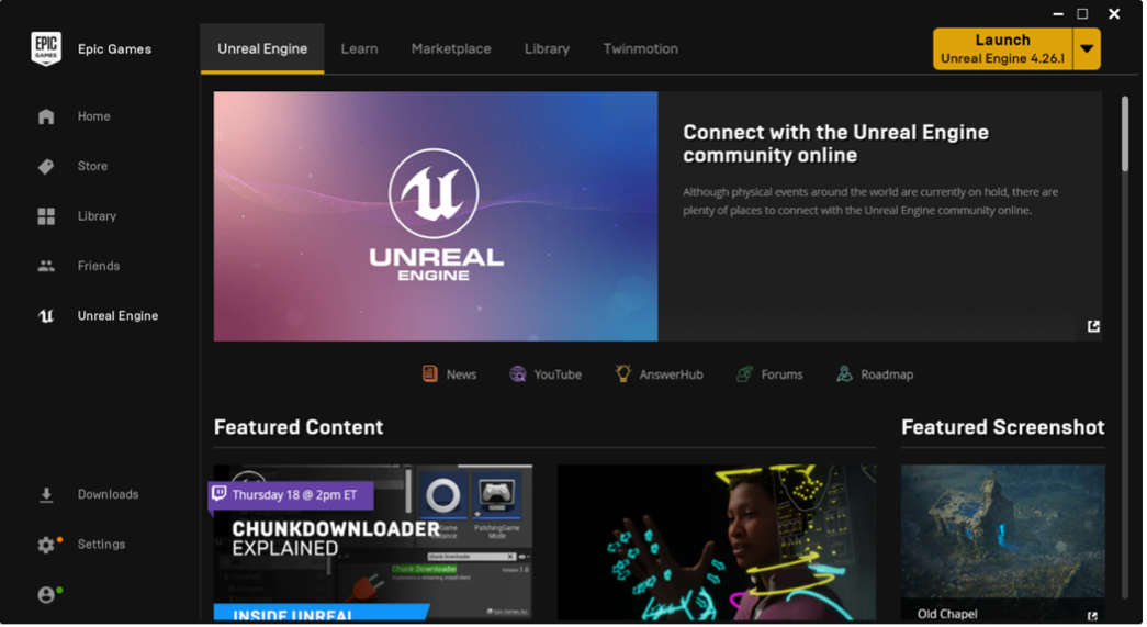
Go to the Marketplace tab:
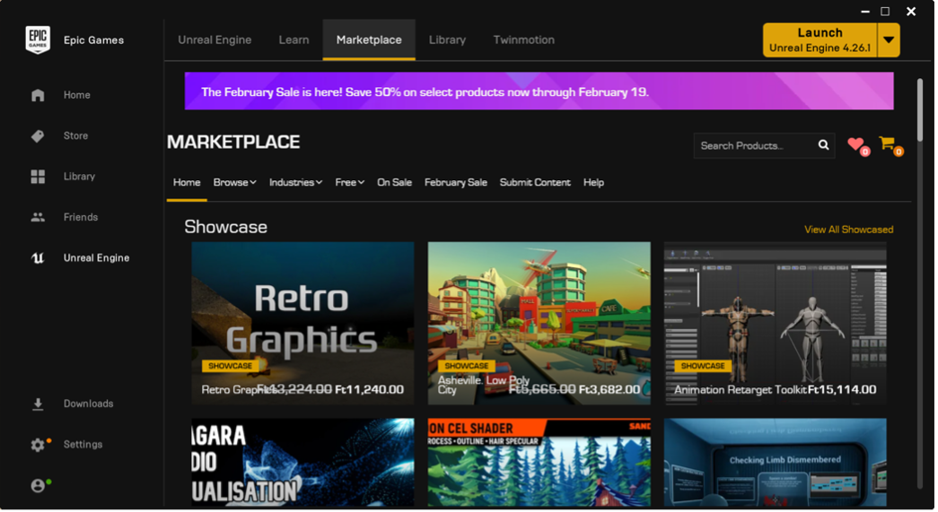
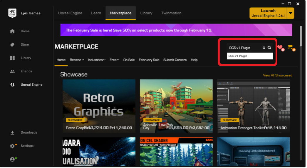
Search for the “DCS Plugin” and press “Enter” or click the search icon:
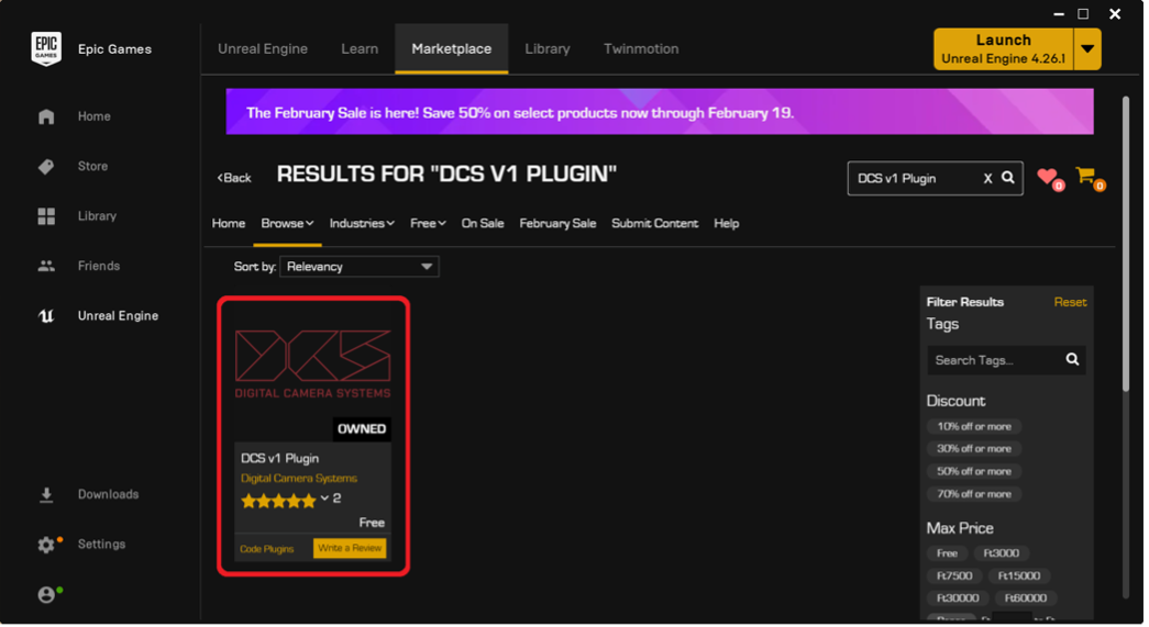
Select the "DCS Plugin":
If prompted with “Free” and “Add to Cart” buttons, select the “Free” button.
Click the Install to Engine button:
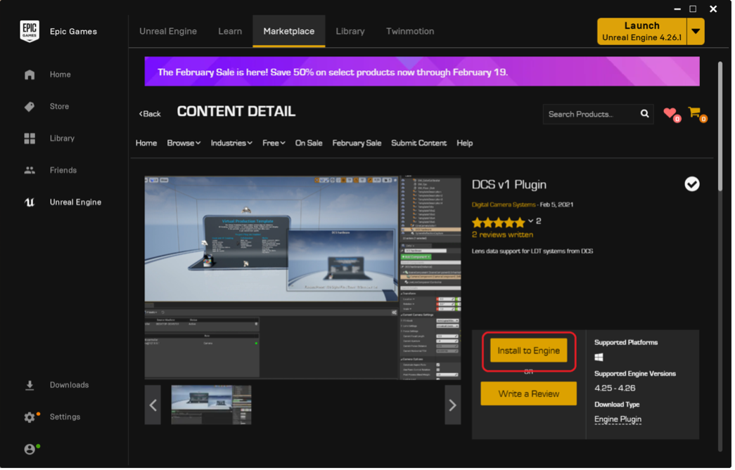
Next, select which engine version will be used with the plugin, then click “Install”.
The progress of the download can be viewed in the downloads tab on the left.
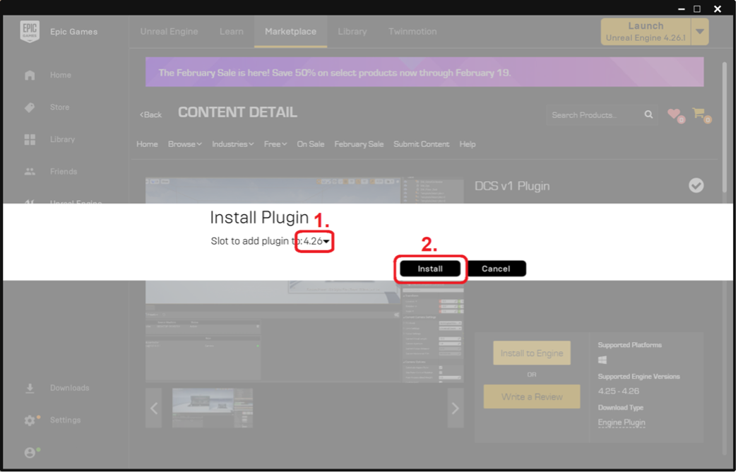
After the installation has been completed, verify that the Plugin has been installed by going to the library menu and clicking on “Installed Plugins”.
At the bottom of this page there is an “Install to Engine” button This is to install the plugin to a different engine version if required at a later date.
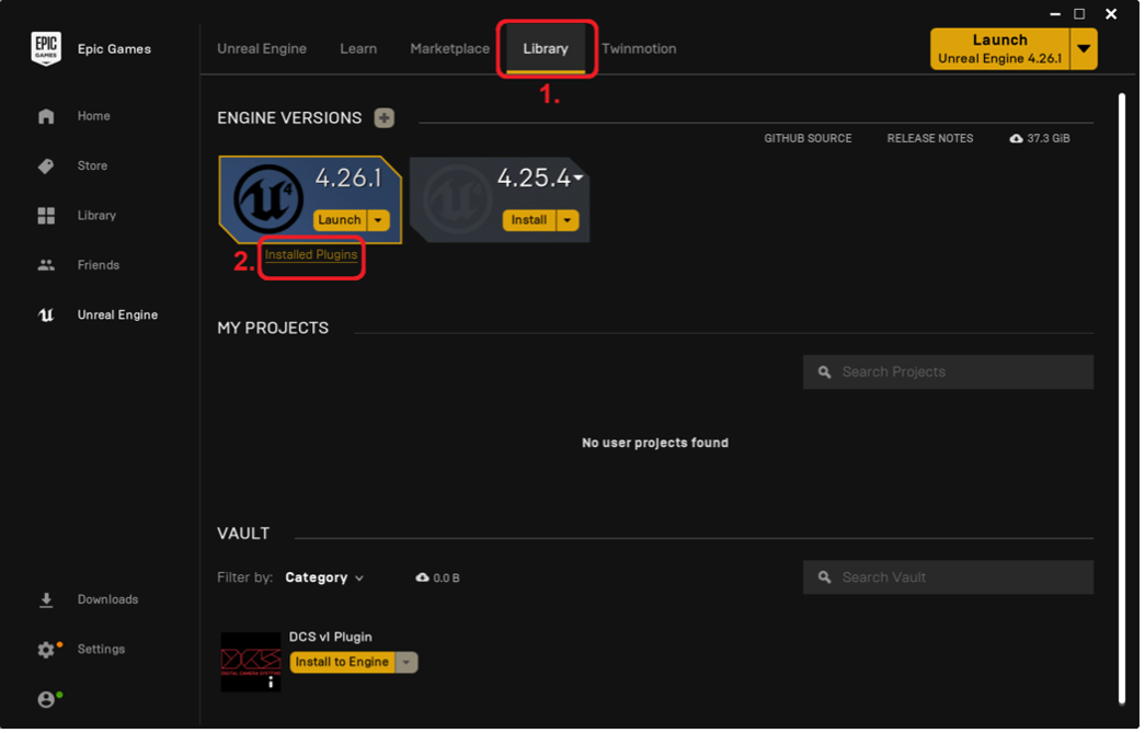
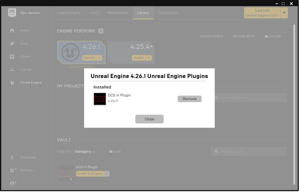
Clicking “Installed Plugins”, shows all the plugins that are installed to the selected Engine version.:
¶ Plugin Quick Start Guide
The following is a guide to setting up a simple project to test the DCS Plugin.
¶ Creating a Basic Project
Start Unreal Engine by running the “Epic Games Launcher” and “Launch” an installed version of Unreal Engine.
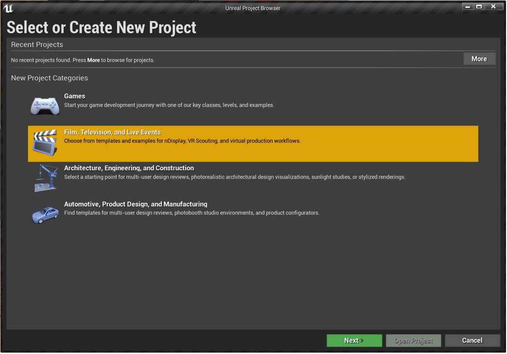
For this example select “Film, Television and Live Events”, then click“Next”:
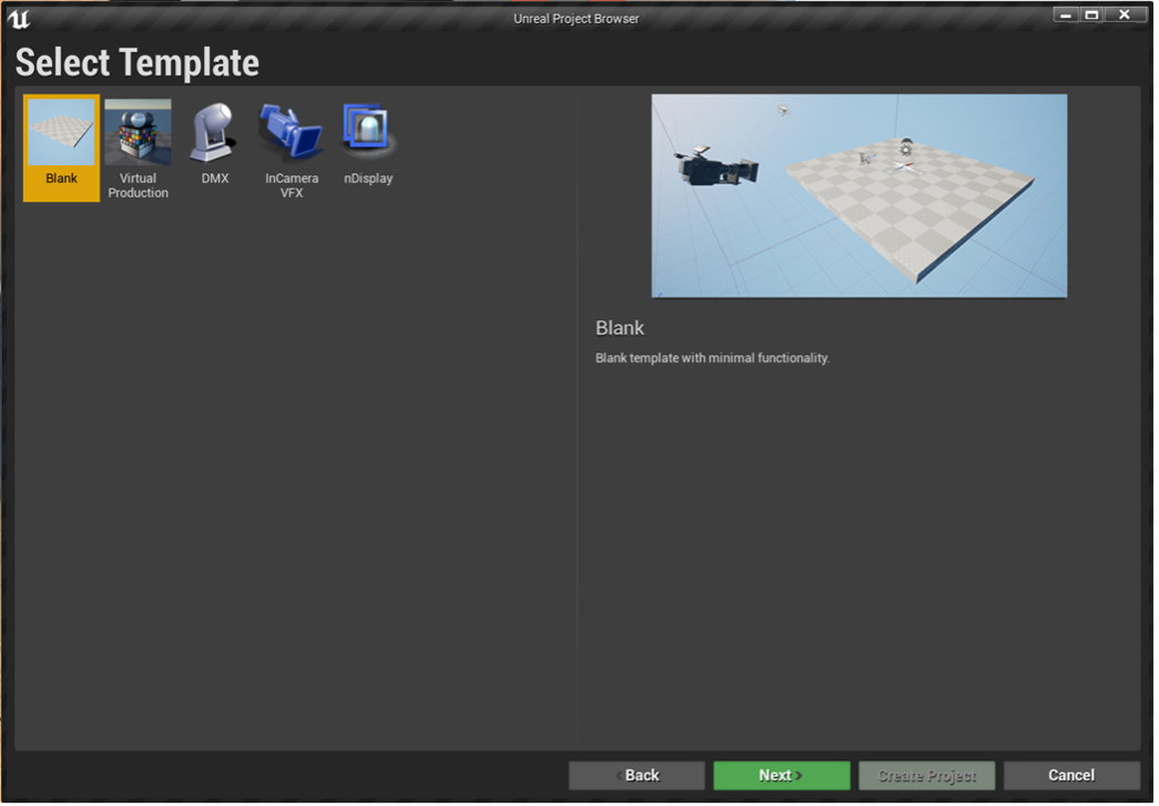
Select “Blank”, then click “Next”:
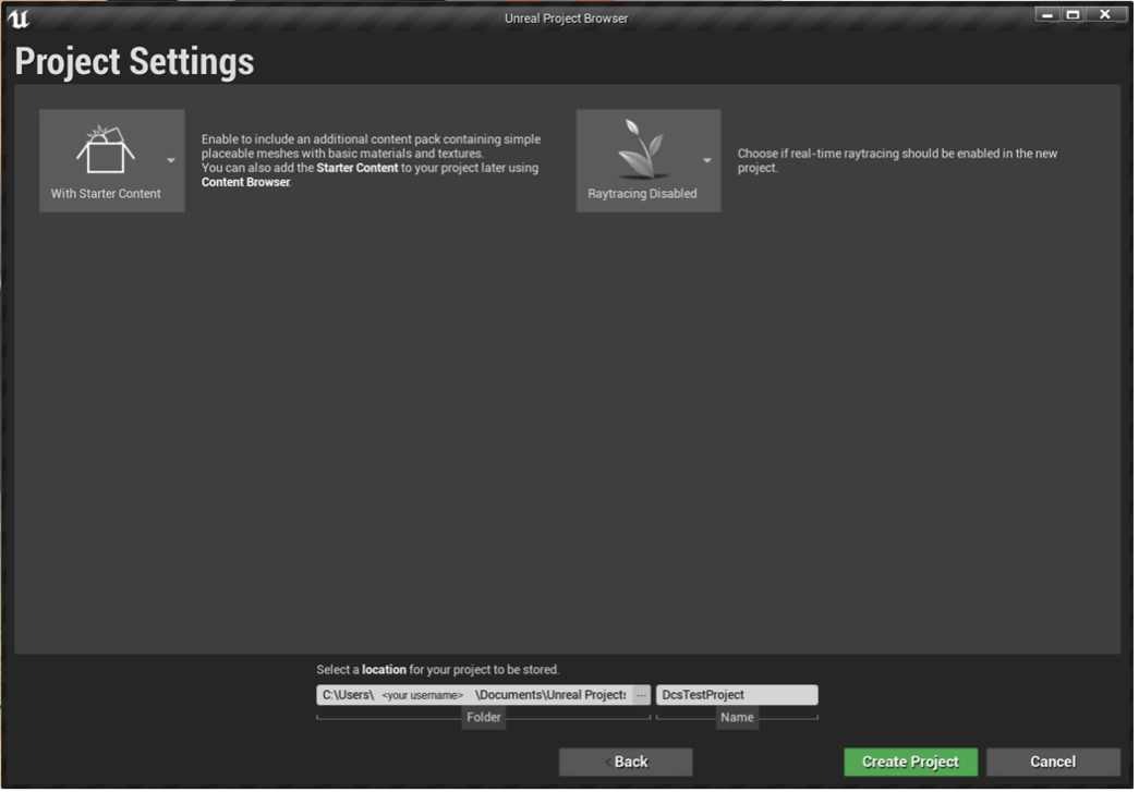
Name the project and click “Create Project”:
¶ Enabling the necessary plugins
To enable the DCS Plugin, select “Edit > Plugins”:
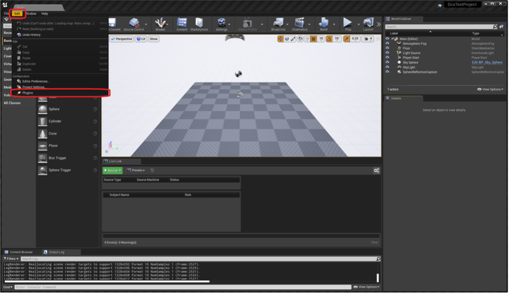
Search for the DCS Plugin and enable it by checking the check box. After enabling the DCS Plugin restart the editor:

¶ Creating a Cine Camera Actor and Connecting it to an External Source
From the “Window” menu select the “Live Link” and “Place Actors” windows. Ensure these are visible:
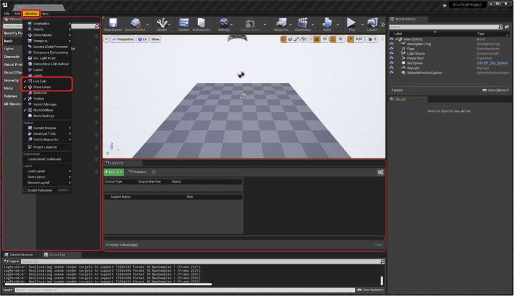
¶ DCS Live Link interface
¶ Source Creation Panel
This is where configuration is done to link the LDT hardware (or data emulator) to the DCS Plugin. In the Live Link window click the “Source” button and select “DCS Live Link Source”. Settings can be left as the default values for this example (further explanation of these fields below). Press the “Create source” button.

Interface: The interface (e.g., ethernet) of the Host PC, which is connected to a network from which you want to receive data. Using “Any” receives data from all interfaces of the current PC.
Port: The default DCS port is 33322. In the instance of the port interfering with other network settings, this must be changed in the settings and on the LDT itself.
Multicast: If joining a multicast network group, enter the group’s IP address. If not using multicast leave blank. Multicast addresses start from 224.0.0.0 to 239.255.255.255.
¶ Source Settings
In the source settings it is possible to:
- add, rename, and delete DCS devices,
- turn on the auto-discovery feature to automatically find and connect devices (Note: if using the LDT Data Emulator, the auto-discovery feature will only work if the emulator sends the “Product Name” and “Product Brand” messages.),
- select the global timecode provider device.


Device IP Address: The LDT’s local IP address. This can be set locally in the LDT menu, further instruction on this can be found here.
Custom Device Name: If adding a device manually, a custom name is required. The created device names will be in the following format: <custom_name>@<device_ip>. Note: There can be multiple devices with the same “Custom Device Name” but there can be only one device with the same Device IP Address. If trying to create a device with an already assigned IP Address, then it will rename that device instead.
Create DCS Subject:
● Create: Creates a device with a specific IP Address and Name
● Rename: Renames the device at the Device IP Address to the currently provided Custom Device Name
● Delete: Deletes a device at the Device IP Address. The Custom Device Name is not required.
Turn on/off auto-discovery:
● Manual: Manually add, rename, and delete devices
● Automatic: The plugin automatically detects DCS devices if they are sending data.
Master Timecode Device: If there are multiple devices added under the DCS Live Link Source, one can be selected as the global timecode.
¶ Select a Master Timecode Provider
To select a DCS device as the Master Timecode Provider, select “Edit” > “Project Settings”:

Search for “timecode”. Under the Timecode tab, select the DcsTimecodeProvider as the Timecode Provider

Once selected the DCS device will provide the global timecode for the project.

¶ Subject Settings
Set buffer delay: The Plugin can delay incoming data from LDT to match latency of other devices. Delay can be by milliseconds or by frames. A buffer will store the incoming data and release it after the specified delay:

Telemetry data: Under the Telemetry data tab all possible data fields that the hardware or the emulator can send can be seen. To specify which data is sent to the Cine Camera Actor enable that data by ticking the box or disable it by unticking the box. This feature is to assist if other 3rd party plugins are providing the same data as the LDT:

¶ DCS Livelink Component
¶ Adding a Cine Camera Actor
Search “Cine Camera Actor” from the “Place Actors” window and drag it to the scene:

¶ Adding a DCS Live Link Component Controller
To connect a Cine Camera Actor with a Live Link subject,select the recently created Cine Camera and click the “Add Component” button. Search for “DCS Live Link Controller” and click on it to add it to the camera.

¶ Connecting a Cine Camera Actor with a DCS Live Link Device
To connect a Live Link subject with the Camera using the DCS Live Link Controller, select the Controller and select a Subject Representation for it. The Subject has to be a Live Link device added through the DCS Live Link Source (see here).

¶ DCS Live Link Component Features
The DCS Live Link Component is a Live Link Controller with extended functionality. If a DCS Live Link Subject is connected to the DCS Live Link Component some of the extended functionality is available under the DCS Live Link Role settings.
¶ Exposure Compensation Interface
The first feature under the DCS Live Link Role is the option to automatically adjust the exposure of the Unreal Engine scene based on the movement of the iris of a real-world lens.

By default, the Exposure Compensation Type is Locked. This means there isn’t any compensation happening.
- Exposure Compensation types:
● Locked: The camera’s aperture won’t affect the scene
● Sync: Based on the Exposure Compensation Zero constant that has been set, the compensation will be calculated and applied to the Camera Actor. By ticking Is Slave changes can be made to the direction of the calculation.
● Sync Outside a Range: When the aperture value is below the minimum, the exposure is calculated as in sync, with the minimum value as zero. The same method is applied when the value is over the maximum, just the zero value is equal to the maximum of the range. While the aperture is between the range the exposure compensation remains 1.
Note: With both “Sync” and “Sync Outside a Range” the constant values are measured in the same way as the aperture value.
¶ Lens Shading (Smart Lens with Xd only)
Shading data can be sent from a Smart Lens with Xd to the DCS Plugin via the LDT. If using this data there is an option in the plugin to to remove, or apply shading to the image.

¶ DCS Live Live Component Blueprint features
To access the DCS data in Blueprints, the Cine Camera Actor needs to be made into a Blueprint object.
Once complete there are two ways to access DCS data:
● Direct Access
● On Recording event

¶ Telemetry Data Blueprint Access
Right click anywhere on the Blueprint Event Graph and select the Get Telemetry Data function. It will return a DcsTelemetryData Struct which can be seperated into various data fields. These display the current values of the device. The values will update as new data is available.

Note: The “On Live Link Updated”event can be used to constantly receive the latest updated values of the “Get Telemetry Data” function.

¶ “On Recording” Blueprint Event
Similar to the “On Live Link Updated” event in the previous section, the DCS “On Recording” event can be added to the Event Graph. Among the other DCS Frame Data fields the DCS Telemetry Data can be found with all the available data fields. The “On Recording” event will be triggered if the hardware is Recording.

¶ Lens Distortion (Smart Lens with Xd only)
Distortion data can be fed from an Xd enabled Smart Lens to the DCS Plugin via the LDT.The DCS Live Link Component Controller will preprocess the data inside Unreal and the Lens Distortion component applies the distortion to the image.
¶ Adding the lens distortion component
Click “Add Component” and search “Lens Distortion”

¶ Selecting a Distortion Source and Apply Distortion
Click “Lens Distortion”, and then from the “Destination Source”, select the LDT Device Live Link subject.

Tick the checkbox next to “Apply Distortion”.

¶ Packaging a Project with the DCS Plugin
¶ Save the DCS Subject Devices as a Live Link preset
The following section covers how to set the scene view to the camera, automatically assign Live Link sources and subjects, and finally, package the Unreal project to an executable file.
Save the added devices/subjects and the source as a Live Link Preset, by selecting “Presets > Save As Preset”
Note: This is an important step. Be sure to connect all devices and save the configuration as a Preset so they can work in the package project (.exe).

Then name and save the preset.

¶ Bind the startup view to the camera and assign the Live Link Preset to the Live Link Client with Blueprints
Open the level Blueprints by clicking on the “Open Level Blueprint” button in the “Blueprints” menu.

Drag the Camera actor that is assigned the to Live Link external device to the Blueprints menu.

Right click inside the Graph editor (checkerboard pattern) and search and add the “Get Player Controller” function.

Right click and search for the “Set View Target with Blend” function and add it to the Graph Editor. This function won’t show until you disable the “Context Sensitive” option.

Connect the boxes in the following way. This function will execute right after the “BeginPlay'' event when the map has been loaded. Target the Cine Camera Actor and assign the starting view instead of the player (First-person) to the camera. The view will now be from the perspective of the Cine Camera Actor. Next, create a new variable on the left of the Blueprint editor.

Select the recently created variable. It isn’t necessary to change its name, however, it is to select a new variable type for it. Search for the “Live Link Preset” object and add it.

Compile the Level Blueprints by pressing the “Compile” button.

The Live Link Preset created earlier can be found in the Content Browser inside the normal Unreal Engine editor. Drag it to the Blueprint editor and set it as the recently created variable’s “Default Value”.

The variable is now set. To create it, drag it to the scene and press the “Get < variable name >”.

Add the “Apply to Client” function to the Event Graph. “Context Sensitive” option needs to be disabled to find this.

At the end, the Level Blueprint’s Event Graph should look like this. Remember to make the connections between the newly added components.
Connecting the Preset is an important step. This way the program knows what devices it should assign to the Client at the start of a packaged project. Once complete, compile the Level Blueprint again.

¶ Verify settings before packaging
Ensure that the “Game Default Map” is set to “Main” (or custom map where the camera was placed). This can be found in this option: “Edit > Project Settings” and search for “Map” in the search bar.

¶ Package project
Once everything has been set to package the project, click on “File > Package Project > Windows (64-bit)” and select a target folder. All the devices saved by the Live Link Preset should work after running the .exe.
