¶ Lens Link Version 2.1.5

This guide is a work in progress as the current Lens Link is not finalised. If more context is required, or issues found, please contact the team via tom.payne@dcs.film.
¶ Introduction
The Lens Link is a wireless transmitter unit that is designed to control supported motors from a greater range.
The Lens Link unit can connect to an LDT-V2 unit wirelessly via a set frequency, which will pass the command to the Preston MDR.
The range can be extended further when an LDT-RX1 unit is used betten the Iris Extender and LDT-V2.
Please note that the Lens Link must be paired with an LDT-V2 and Preston lens control system.
¶ Current Firmwares
- Lens Link - 2.1.5
- DCS Bridge - 2.1.4
- LDT-RX1 - 2.1.4
- LDT-V2 - 1.64
¶ Lens Link Compatibility
- (LDT-V2)
- (LDT-RX1)
- (DCS Bridge)
¶ Physical Connection
| Name | Type | Description | Cable Codes |
|---|---|---|---|
| PWR | 2pin 0B Lemo | Power for the LDT-RX1 | PWRE |
| ETH | RJ45 | Ethernet connection port | Ethernet cable |
¶ Mounting
The Lens Link has a hole to mount the unit to a 3/8" stand.
¶ Antenna
The Lens Link compatible with any SMA male antenna which works between 2200-2500 mhz freq.
¶ Frequency information
The Lens Link can work at any frequency between 2200mhz and 2500mhz. This is configurable in the settings.
Ensure the Lens Link is set to the same frequency as the LDT-V2, DCS Bridge or LDT-RX1.
Please note that the DCS wireless system only works between DCS branded products and requires an LDT transmitter and receiver. For instance an LDT transmitting device (such as the LDT-V2/DCS Bridge) cannot be connected to a 3rd party router or other receiver and must be paired with a LDT reciever (such as the LDT-RX1).
¶ Configurations and Workflow
For a visual breakdown of configuation options, please see this document: INSERT LINK
Each set up requires
- Ensure each unit is powered correctly.
- Ensure the Lens Link and LDT-RX1 are on the same network.
- Confirm the frequencies are shared between desired units connection strength is stable.
¶ Lens Link direct to DCS Bridge
-
Ensure the correct 'Axis' is selected to automatically control the desired axis.
-
Choose: `Main Menu > Control Route > Local TX
This will enable the Lens Link's Sub-WiFi communication.
- Change the Lens Link frequency to match the target DCS Bridge.
Preset frequencies can be saved via the WebUI to swap between targeted rigs more easily.
- Ensure the correct 'Axis' is selected to automatically control the desired axis.
The axis enabled on the Lens Link will block other Preston handsets from taking control. Set the axis to 'off' to release control back to the Preston.
¶ Lens Link direct to LDT-V2
- Choose: `Main Menu > Control Route > Local TX
This will enable the Lens Link's Sub-WiFi communication.
- Change the Lens Link frequency to match the target LDT-V2.
Preset frequencies can be saved via the WebUI to swap between targeted rigs more easily.
- On the LDT-V2 unit, enable the desired axis to control.
- Choose: `Menu > Settings > Advanced > Motor control'
- Then enable control for the desired axis.
This axes enabled on the LDT-V2 will block other Preston handsets from taking control. Simply disable the axis on the Lens Link to restore control.
¶ Lens Link via an LDT-RX1
¶ LDT-RX1 to Bridge
- On the LDT-RX1, check that Production Network is set to 'On'.
- Ensure the frequency is the same between the desired LDT-RX1 and a target Bridge.
¶ LDT-RX1 to LDT-V2
-
Ensure the frequency is the same between the desired LDT-RX1 and a target LDT-V2.
-
On the LDT-V2 unit, enable the desired axis to control.
-
Choose: `Menu > Settings > Advanced > Motor control'
-
Then enable control for the desired axis.
'Production Network' must be enabled via the WebUI for both the Lens Link and LDT-RX1 units.
¶ Multizone
This setup requires multiple LDT-RX1 units to be connected to the same network. These should be places around the area that the camera will be.
The Lens Link will identify which unit is closest to the camera and send the command in the most direct route.
¶ Recommended setup order
- Set up the Lens Link Handset first,
- Set up RX1 if required, add to users network,
- Set up unit on the camera, Bridge or V2. Ensure each camera unit is set to a different frequency.
¶ Rigging the Lens Link
¶ Setting up the Lens Link
-
Power the unit via either PWRE cable (mains power), or via a battery (same as Preston battery).
-
Navigate the menu to select the frequency matching that of the target LDT-V2.
¶ Menu Navigation
The unit has 3 buttons.
From top to bottom, these will be referenced as 1, 2 and 3.
¶ 1: Max Button
- Hold - Sets limit at top end of map
- Tap - Toggles the limit on and off
¶ 2: Min Button
- Hold - Sets limit at bottom end of map
- Tap - Toggles the limit on and off
¶ 3: Enter Button
- Hold - Access the menu
- Tap - Back
¶ Setting Limits
A yellow light will show on the knob when the lens command is within a limited area of the map
¶ Lens Link Map Creation
Prior to this, ensure the lens had motors attached and calibrated successsfully with no motor slip.
Ensure that the correct axis can be controlled by the Lens Link Handset.
- Menu > Knob > Lens Map > Add Lens
- Set the 'Brand' name
- Set the 'Type' name
- Insert last 3 digits of the len's serial number
- Move to a mark on the intended lens axis
- Select 'Add Mark' and input the value.
- Move to the next Mark on the lens and repeat the steps until all marks are inputted.
- The lens will automatically be saved and loaded.
¶ Lens Map Selection
Manual selection should be enabled in the mapping menu, in order to choose a Lens Link created map.
This is only required when using the DCS Bridge, as LDT-V2 maps do not require seperate maps to be built.
When running the Lens Link firmware 2.1.4, V2 maps will be pulled automatically from the currently linked LDT-V2 unit. Alternate Lens selection methods will not be shown on this firmware.
The map shown on the Lens Link is for reference only and will not be recorded or injected into the camera.
¶ Setting up the LDT-RX1
The LDT-RX1 must be connected to the same network as the Lens Link.
- Power the LDT-RX1 via POE with an ethernet cable or use the PWRE cable.
- Ensure an Antenna is attached to all relevant units.
This can be done by altering the 'Unit IP' via the WebUI. A powercycle is required for the new IP address to be activated. When complete, the WebUI can be accessed via the new address.
The Frequency should match an LDT-V2 or DCS Bridge unit. By pairing an RX1 with a unit on the camera, the Lens Link can quickly switch between cameras by simply changing the frequency.
The light next to the antenna will indicate if it has a stable connection to a unit sharing the same frequency. Red means that there is no active connection. Green means that is is communicating via sub-wifi frequency successfully.
¶ Setting up the DCS Bridge
The DCS Bridge should be used when either no lens data recording is required, or when using an LDT for an ALEXA camera.
In the WebBrowser, ensure that the correct connection type is enabled.
For the Bridge connecting directly into the Preston MDR unit,
¶ Setting up the LDT-V2
-
The unit functions the same as the R2 unit - all settings should be chosen to continue normal usage.
-
Access ‘Settings > Advanced > Ext. MDR Control to enable the desired axis
The frequency of the LDT-V2 is 2405 by default.
This can be altered via ‘Settings > Frequency’
¶ Settings
The LDT-RX1 and DCS Bridge settings are controlled by a built in web interface.
Network settings selected on the LDT-V2 will not be used if connected to the LDT-RX1. The LDT-RX1 settings take priority and will be utilised.
¶ Accessing the LDT-RX1/DCS Bridge Settings
¶ Navigation
- Frequency
- Alter digit 1
- Alter digit 2
- Alter digit 3
- Alter digit 4
- Camera List (Saved Frequency and Naming can be altered via the webUI)
- 2281 - Camera A
- 2395 - Camera B
- 2289 - Camera C
- 2287 - Camera D
- 2285 - Camera E
- 2283 - Camera F
- 2281 - Camera G
- Gateway
- Alter digits
- Netmask
- Alter digits
- IP Address
- Alter digits
- Led Bright
- Low
- Medium
- High
- Axes
- Iris
- Zoom
- Focus
- Off
- Axes
- Remote RX1
- Local TX
'Camera list' - Preset frequencies.
'Axes' - Choose which lens axis to control.
¶ Status Lighting
The light on the knob will alter it's colour to signify key information.
¶ White/Purple
- Normal use
¶ Yellow
- In the zone of a set limit
¶ Interface
Loss - How strong the connection is
- 0% - Strong signal
- 100% - No Signal
¶ Lens Link WebBrowser Navigation
Settings can be adjusted on either the Handset menu or via the WebBrowser. Additional settings can only be found on this Web Interface, such as naming preset frequencies
¶ Status
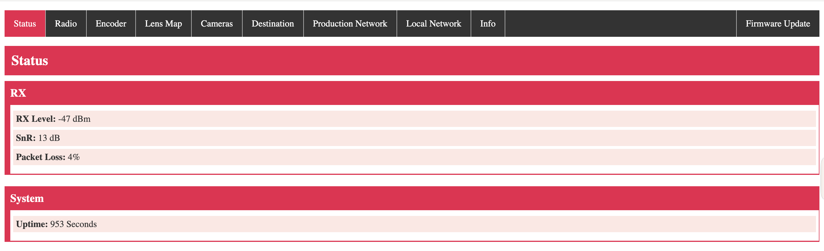
The Status Tab shows the connection to other LDT units.
- RX Level: Connection Status
- SnR: Connection Status
- Packet Loss: How strong the connection is. Lower values indicates a stronger connection.
- Uptime: How long the unit has been powered for.
¶ Radio
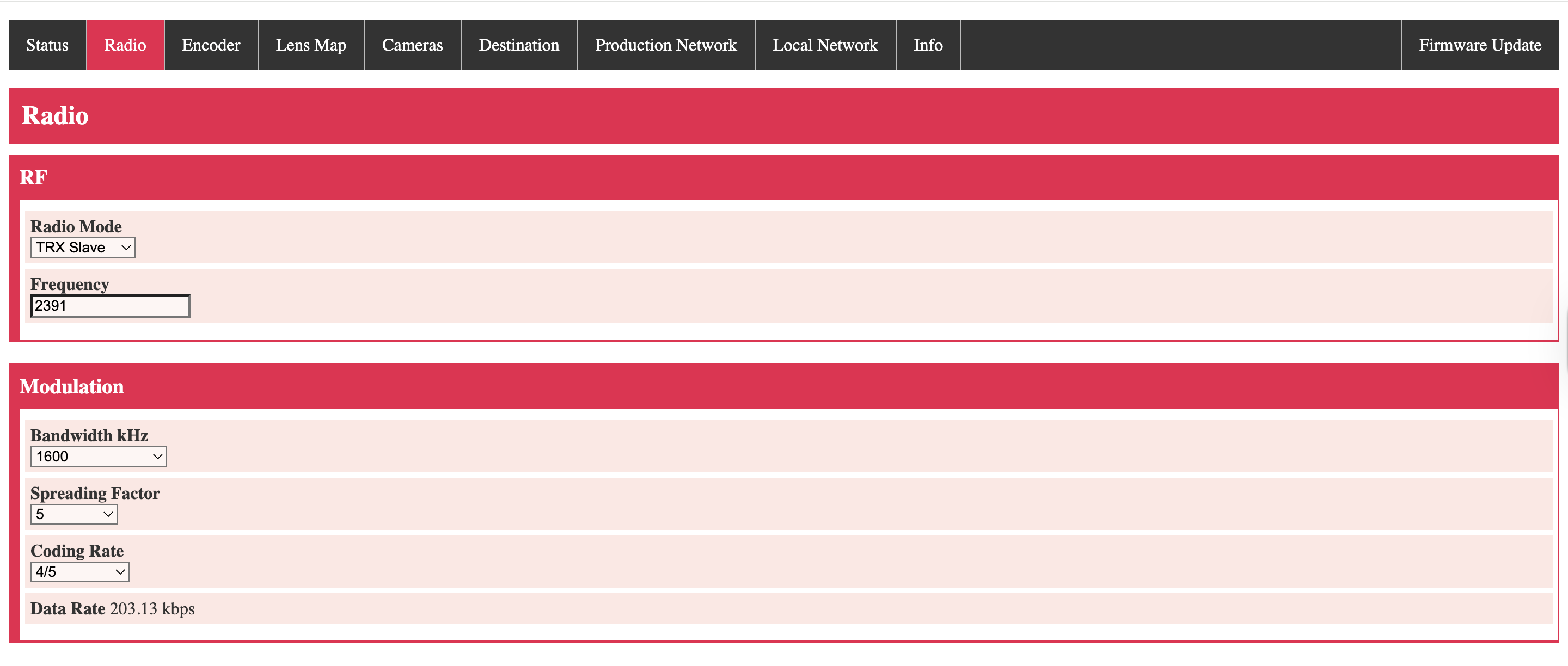
The Radio Tab allows for changes to the connection and data type.
- Radio Mode: Affects the devices role (Best left on default)
- Frequency: Selected Frequency between 2200-2500mHz (use to pair a set of devices)
- Bandwidth kHZ: 1600 (default)
- Spreading Factor: 5 (default)
- Coding Rate:4/5 (default)
- Data Rate: 203.13kbps (default)
¶ Encoder
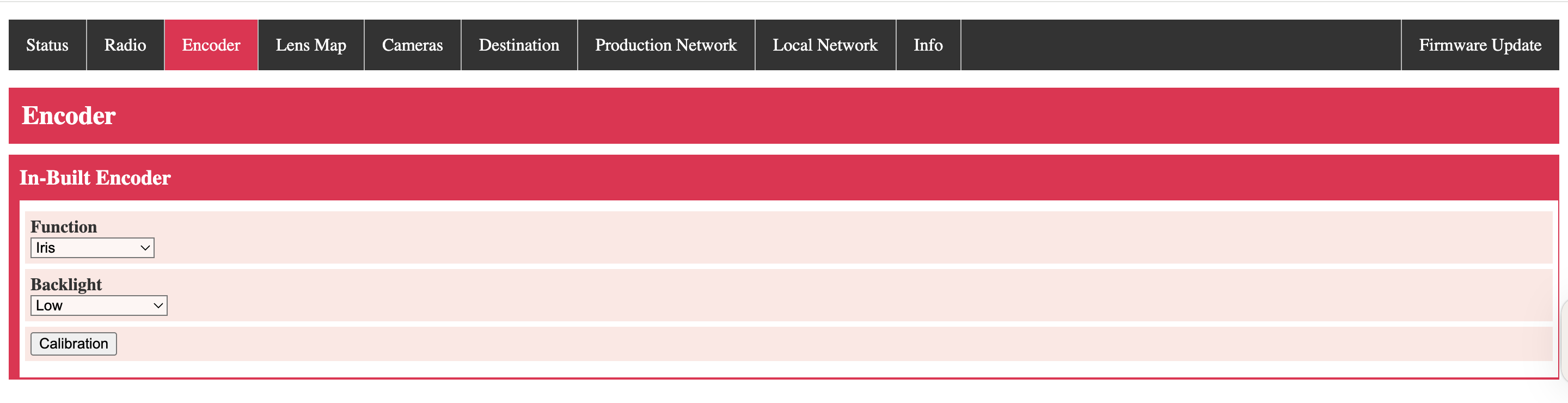
-
Function: Which lens axis should the Lens Link control
(If using the LDT-V2, the relevant axis must be selected on the V2 handset. The Bridge will select automatically.) -
Backlight:
¶ Lens Map
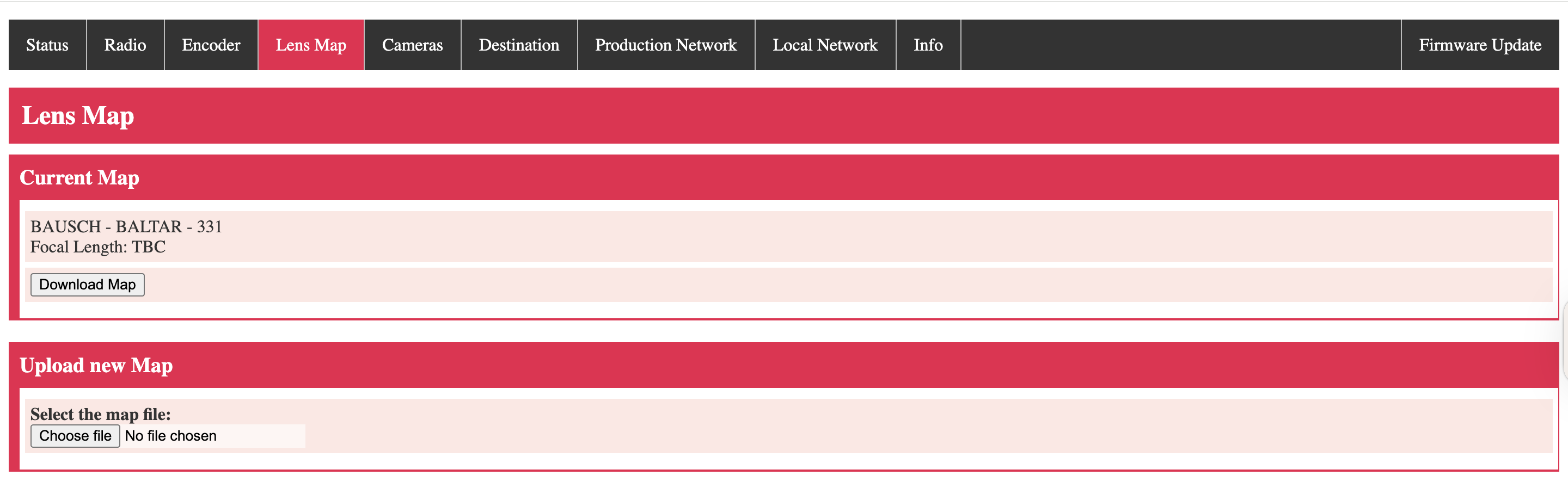
This tab allows users to load lens maps from an existing XML file, made by an LDT-R2/V2/F1 unit.
As of firmware 2.1.5, multiple lens maps can be uploaded and stored on the handset. These maps are .xml files, created via the LDT unit.
If a map is created with the handset alone, then the map will be present on the list.
Firmware 2.1.5 has a bug that prevents the 'Download Map' and 'Delete Map' from working. Future versions corret this issue. If using this fw, deletion via the handset's menu will still function correctly.
¶ Cameras
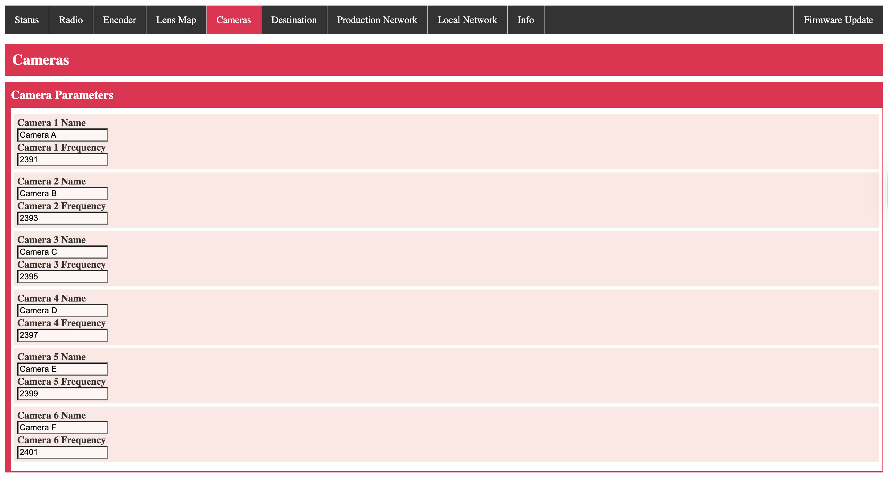
This Camera tab offers the ability to set preset frequencies to communicate to the DCS unit on the camera. The name and frequency can be modified.
The saved options can be quickly chosen on the handset's menu under the camera section.
¶ Destination
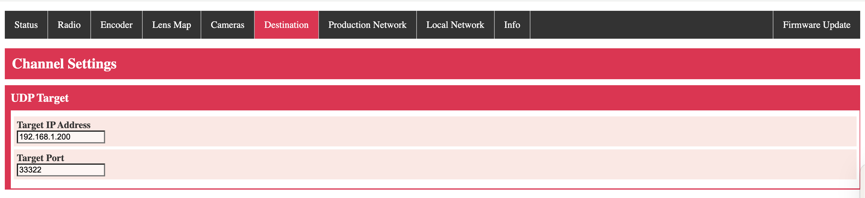
This address is the target IP. This setting does not need to be altered. Only the Local Network unit IP is required to connect to a new network.
¶ Production Network
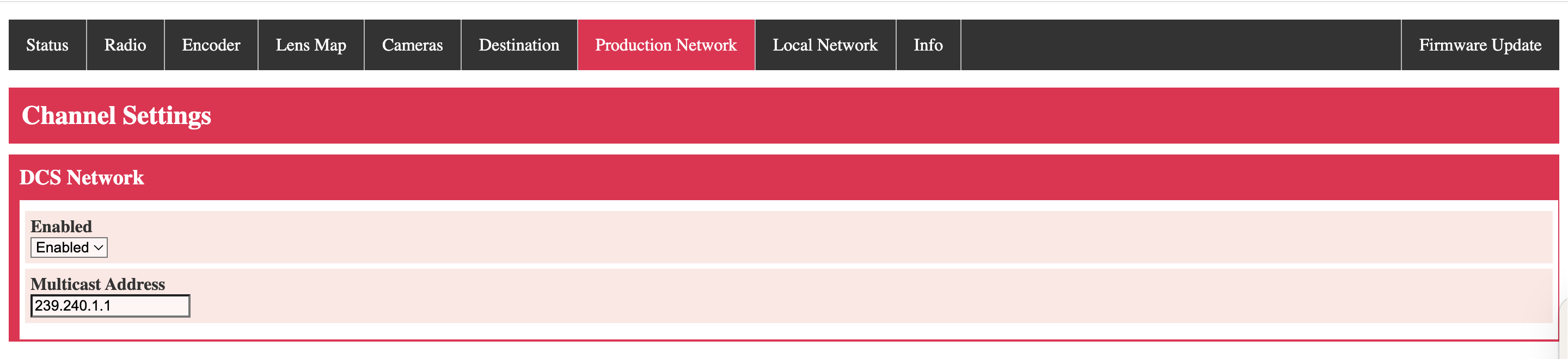
This option should be enabled to allow the user to connect to an LDT-RX1 on the same network.
¶ Local Network
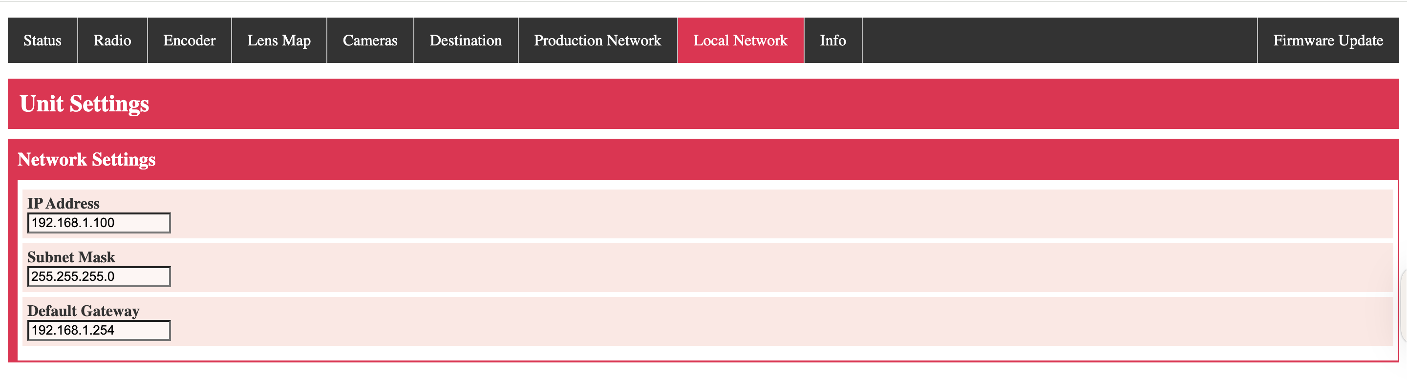
This menu shows the current IP address of the unit. Alter this to connect onto the desired network. Changing this will affect the IP address needed to access the WebUI upon a reboot.
¶ Info
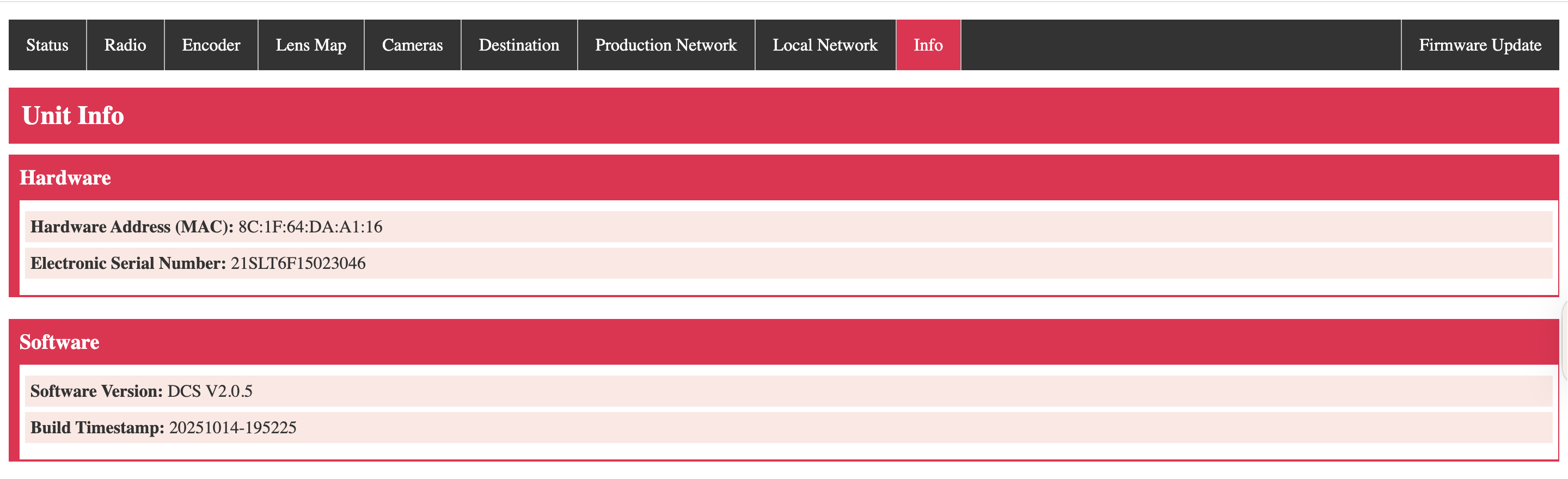
This section covers Lens Link unit information that is benifical for troubleshooting with DCS remotely.
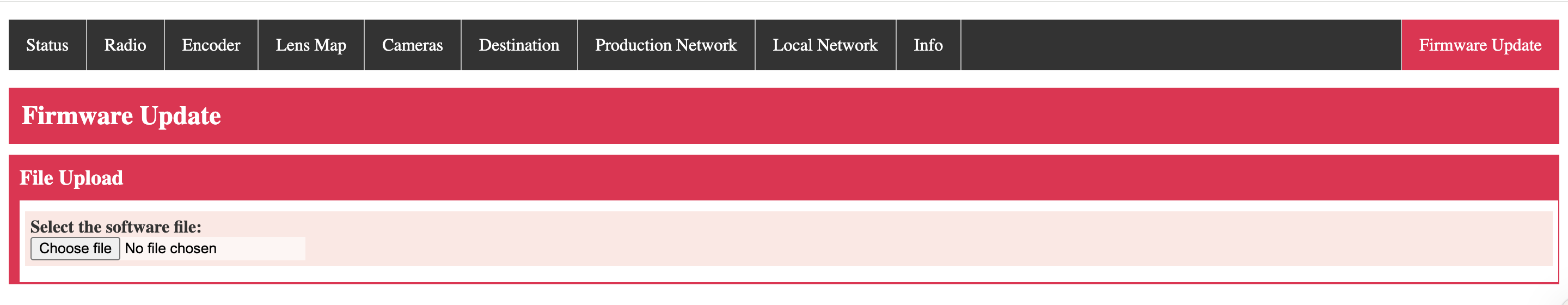
¶ Firmware
¶ DCS Bridge/LDT-RX1 WebBrowser Navigation
DCS Bridge settings can only be adjusted via the WebUI. Users should access this to set the units frequency or connect to a specific network.
This guide will highlight Tabs related to the Lens Link workflow. For additional information about these specific units, please refer to the Bridge and RX1 guide. LINK
¶ EXT Port (Bridge Specific)
IMAGE
The Ext Port Tab shows the current function of the DCS Bridge unit. Select what the DCS Bridge is directly connected into.
- External Connection - Which unit
- Cooke / Zeiss - Enables Smart Lens streaming (Not for Lens Link usage)
- LDT-M2/A2 - Using the pass-through serial port on the relevant LDT unit
- Preston MDR - Connected directly to Preston MDR serial port directly
¶ Production Network (RX1 Specific)
The Production Network multicast should be enabled to allow for streaming Lens Link commands.
If using multiple RX1 units on the same address, set the multicast IP address to a different value for each unit.
¶ Unit
IMAGE
The Unit Tab shows shows the LDT's current IP address. If this is altered, the unit will use the new address upon a reboot. Alter this to connect to a specific network.
¶ Additional Functions
¶ Resistance adjustment
The knob resistance can be increased or decreased between 1-9 values. Simply turn the dial on the side of the knob to adjust to the users preference.
¶ Troubleshooting
-
Bridge cannot control motors
What mode is it set to? If connection is Bridge direct into an MDR, then use Preston MDR control in the WebUI. -
V2 cannot control motors
Enable the desired axis in Motor ext. This will lock out other preston handsets from controlling that axis while active -
V2 blocking preston motor from working
Disable the required unit from the motor EXT menu -
The knob hardstops do not match the lens, leading to motors jumping
The Lens Link knob reqires a calibration. Inside the knob menu on the Lens Link, select calibrate. Set the knob to an anti-clockwise position when prompted. Confirm and follow prompt to the other end. This will enable to knob to match with the data map.