| v1.0 | 28/12/2020 |
¶ Introduction
The DCS Ethernet to serial convertor is designed to be used with DCS' LDT range.
Configuration is done in an embedded webpage in the device.
¶ Specifications
¶ DC Power:
Connector: Lemo 0B.302 single keyway, compatible mating connector is FGG.0B.302.CLADxxx
Voltage: 9-36VDC, reverse polarity protected
Pinout:
| 1 | 0V – (100kOhm to Chassis) | ||||||
| 2 | 9-36V DC |
¶ RS232
Connector: Lemo 0B.304 single keyway, compatible mating connector is FGG.0B.304.CLADxxx
Interface levels: True RS232, +/- 6V out +/- 25V in (maximum)
Data Format: Selectable
Pinout:
| Pin | Function | Information |
|---|---|---|
| 1 | Not connected | |
| 2 | Ground | Chassis Ground |
| 3 | RS232 | Configurable as Input/Output, Factory set as Input |
| 4 | RS232 | Configurable as Input/Output, Factory set as Output |
¶ Ethernet
Connector: RJ45
Speed: Auto-negotiation 10/100 Mbps
¶ Configuration
The configuration of the unit is done via navigating to the embedded webpage in the unit using a standard web browser (tested with Chrome). The IP address of the unit must be in the same subnet as the computer attempting to reach it.
Once a connection with the webpage has been established, a prompt for a username and password should appear. By default, both of these fields are blank, clicking on OK should get through to the settings.
After adjustment of settings, the user must remember to click “Apply Settings” for the changes to take place. The unit will apply and restart.
¶ Network Settings:
The network settings tab allows configuration of the IP address used, which can be static (user defined) or automatic. In local area network operations, the “Default Gateway” and “DNS Server” fields can often be left blank.
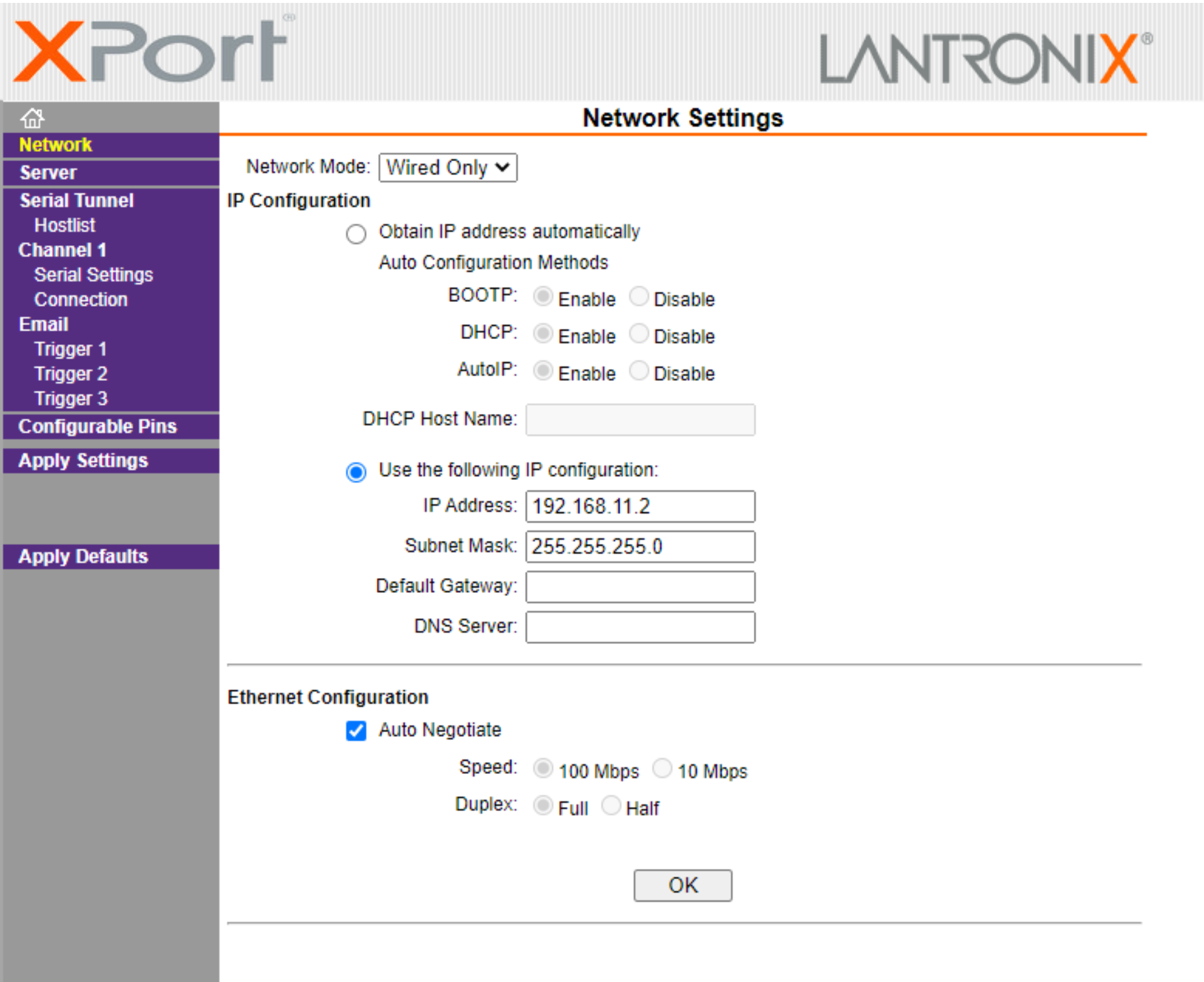
If the new IP address is on a different subnet, it is likely the connecting computer will need to be reconfigured after the settings have been applied.
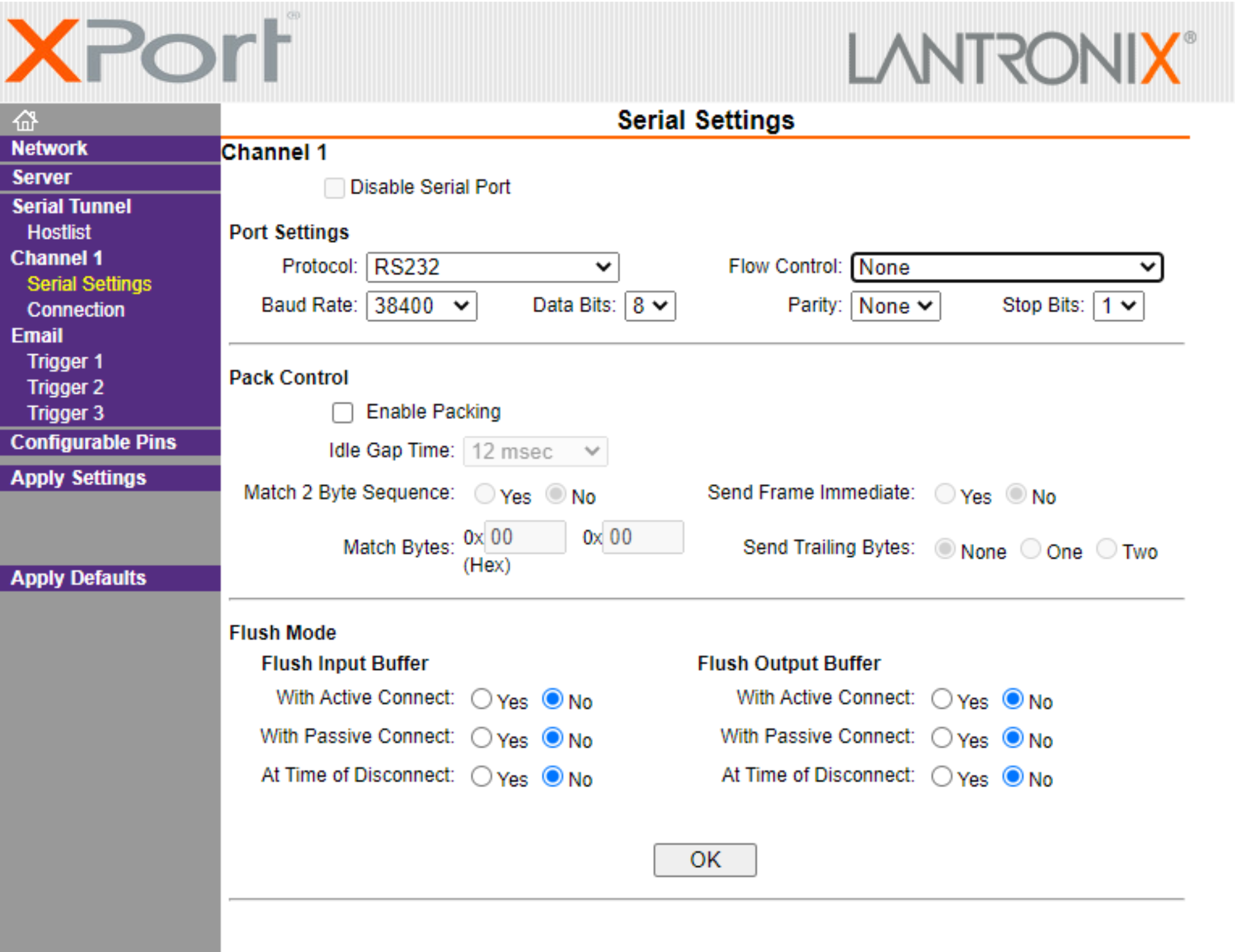
¶ Serial Settings
The serial configuration can be set under the tab “Serial Tunnel” -> “Channel 1” -> “Serial Settings” The “Protocol” must be set to “RS232” and the “Flow Control” set to “None”. The other port settings should be matched to the serial device being communicated with.
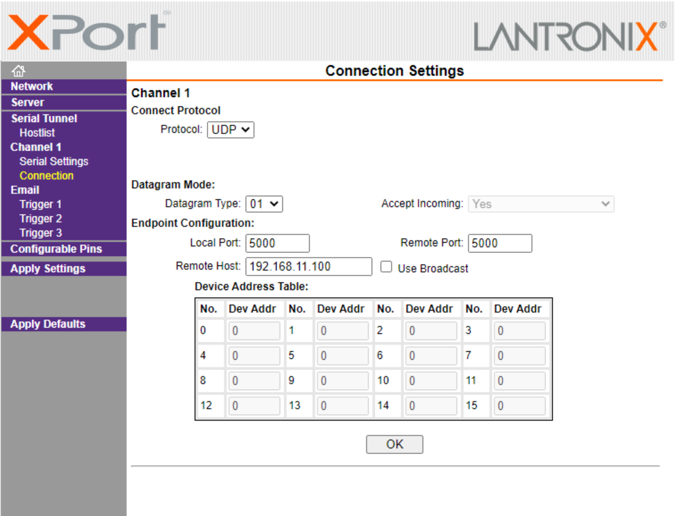
¶ IP Endpoint Settings
The IP settings of the remote device are configured under the tab “Serial Tunnel” -> “Channel 1” -> “Connection”
For UDP unicast data, the “Protocol” should be set to “UDP”. The “Datagram Type” should be set to “01”.
The “Remote Host” is the IP address of the targeted IP device. The “Remote port” is the port to be addressed at the remote host.
The “Local Port” is the port that data is sent from. If the “Accept Incoming” is set to “Yes” this is the port that incoming UDP data should be set to.
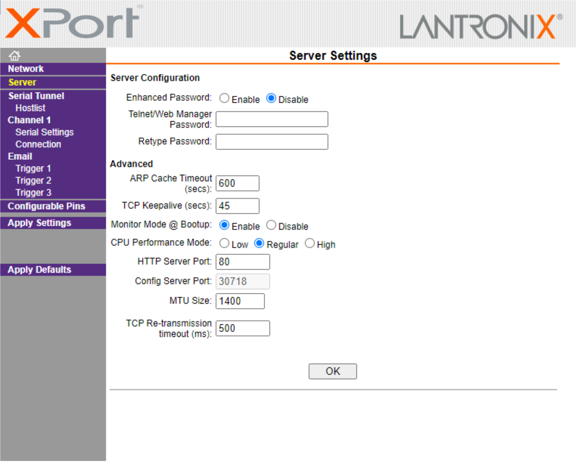
¶ Server Settings
It is possible to add a password to the device to stop unauthorised adjustments, this can be found under the “Server” tab.
¶ Device Discovery
The ETHtoSRL unit will have a preconfigured IP address printed on the housing. Should this not work, please download an IP scanner to search the local area connection for devices and list their current IP addresses.
Some IP scanners may require all firewalls to be disabled to work.
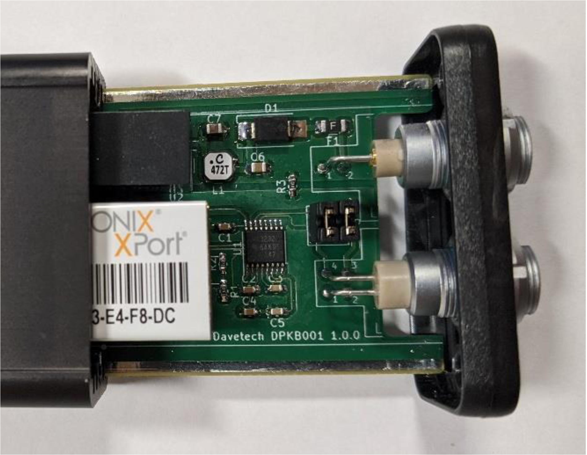
¶ RS232 Pin Settings
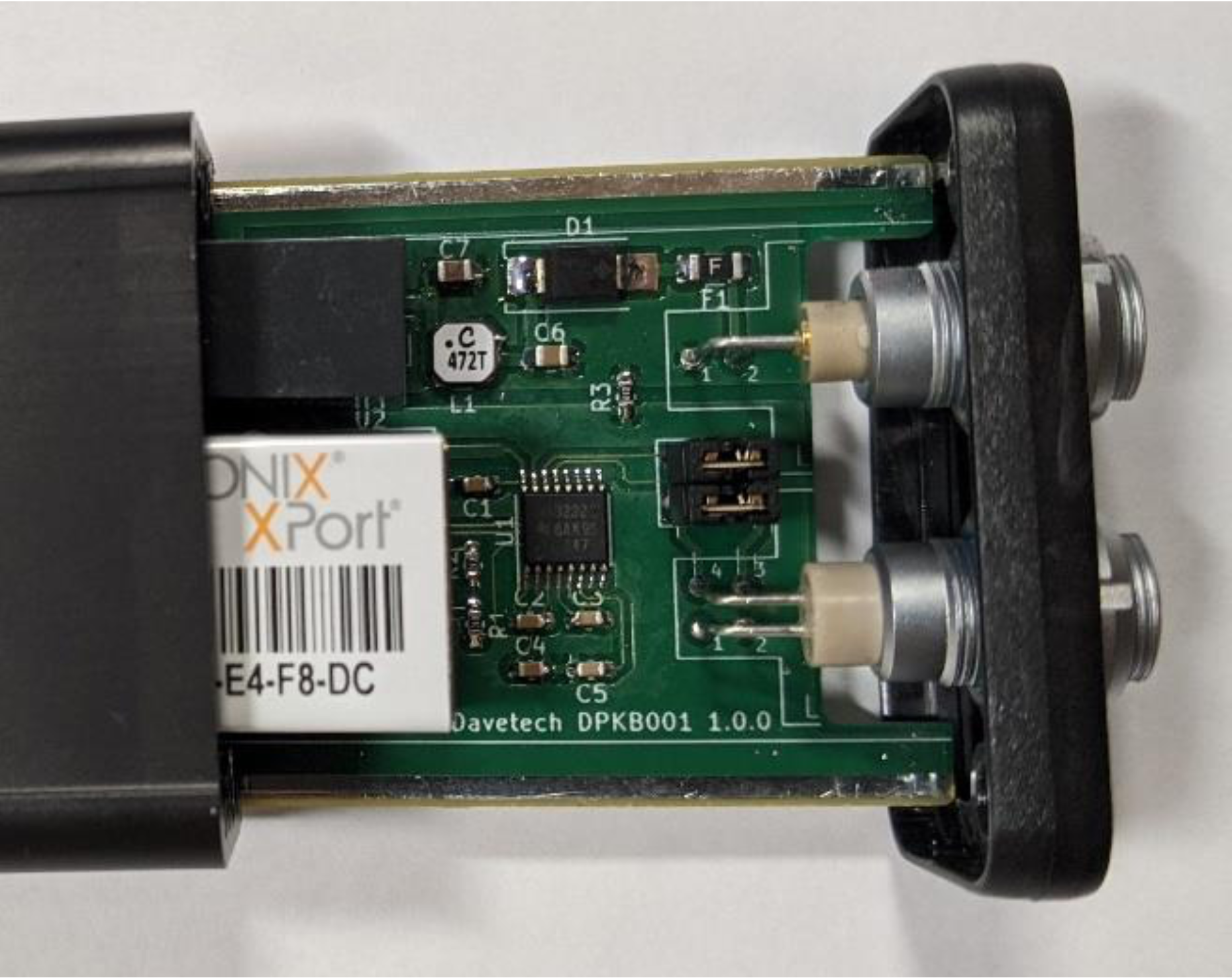
The RS232 Input/Output on the 4 pin Lemo can be configured internally.
To dismantle, remove the 2 off Philips no1 screws from the plate with the Lemos attached. Gently pull the metal plate, and plastic surround out of the unit. The Lemos and the PCB should slide parallel with the long edge of the unit. A gentil push on the RJ45 may assist if the unit is stiff.
The configuration jumpers are between the 2 Lemo connectors.
The jumper positions and their corresponding pinouts are below:
| Pin | Function |
|---|---|
| 1 | Not connected |
| 2 | Ground |
| 3 | RS232 RX (Data In) |
| 4 | RS232 TX (Data Out) |
| Pin | Function |
|---|---|
| 1 | Not connected |
| 2 | Ground |
| 3 | RS232 TX (Data Out) |
| 4 | RS232 RX (Data In) |